- PSRU Implementations -
An Overview of the Various Approaches
NOTE: All our Products, Designs, and Services are SUSTAINABLE, ORGANIC, GLUTEN-FREE, CONTAIN NO GMO's, and will not upset anyone's precious FEELINGS or delicate SENSIBILITIES.
There are several contemporary approaches to PSRU implementation. They include toothed-belt drives, link-chain drives, planetary reductions, helical and spur gear reductions. Each approach has its advantages and disadvantages.
TOOTH BELT DRIVES
Belt drives are light, simple, and inexpensive. Those features have led to numerous attempts at belt-drive PSRU's. Those belt drive units are often claimed to provide lots of torsional cushioning between the engine and prop (after all, it's a rubber belt, isn't it?), but those claims are yet another example of the Wishful Thinking Engineering which is rampant in the experimental aviation community.
In fact, based on data supplied by manufacturers of high capacity tooth belts, the high capacity belts typically used in PSRU's depend on imbedded fibers of high strength polymers for their strength, and consequently, they have substantially higher linear stiffness than common chain drives. That fact alone should be sufficient to show that there is no significant cushioning provided by a tooth belt, despite the intuitions that suggest otherwise.
The major issues with toothbelt drives can be summarized as follows:
- The belt-PSRU’s are limited in power transmission capability;
- Contrary to many marketing claims, the belt in toothbelt-PSRU’s PROVIDES ABSOLUTELY NO TORSIONAL ABSORPTION CAPABILITY (In fact, many of the high capacity toothbelts available have greater stiffness than chains of similar capacity);
- Most belt-PSRU’s do not handle hydraulic constant-speed propellers;
- With belt-PSRU’s, typically, the life of the belt is limited to two or three hundred hours at the loads imposed by a piston engine, which can affect reliability considerations;
- Fixed-center, belt-PSRU’s without a preloaded idler system (spring, hydraulic, etc.) are unable to maintain the correct belt preload in the
dramatically-varying temperature environments encoutered in an aircraft application.
(That issue has MAJOR implications, discussed in THIS PAGE detailing the engineering of Belt Drives, and summarized in the next paragraph.)
In order for ANY belt drive to operate correctly, a certain amount of preload is required (covered in detail in our BELT DRIVES section). The high capacity toothbelts are made from fibers which cause the belts to shrink with increasing temperature, and conversely, expand as they get cooler. The metal sprockets and housings, often aluminum, behave just the opposite, and expand as temperature increases. The net result is that the belt preload, typically set in a hangar environment, increases dramatically as the temperature of the components rises from the setup temperature, and conversely, decreases in colder temperatures. It was this very issue that caused an aftermarket belt drive in a popular experimental helicopter to snap a large number of transmission shafts in flight, leading to unanticipated flight termination (and in many cases, aircraft termination as well).
And then, there's the little issue involving the major supplier of high capacity toothed belts, which threatens Very Bad Things to anyone caught using their products on anything connected with aircraft.
LINK-CHAIN DRIVES
Transmission systems using high capacity link-chains have been around for many years. Link-Chains are commonly used in various different industrial applications, are currently used in several 4-wheel-drive automotive transfer cases, and were used for a short time on early front-wheel-drive automobiles (Anyone remember the Toronado?)
Link-chain PSRU’s have the features of simplicity, the potential to use a hydraulic constant speed propeller, and a fair amount of in-service experience. However, unless the drive is properly designed, the chains elongate in the highly-loaded, torsionally-active aircraft piston-engine environment, and therefore can exhibit relatively short life in aircraft applications.
Fred Geschwender’s link-chain reduction used a 2” wide Morse Hy-Vo™ chain. It has been used successfully in several applications, including ag-planes and the early version of the LEGEND aircraft. However, the torque capacity for a 2" Hy-Vo (from Morse engineering data) is about 440 lb.-ft. at 4000 RPM, decreasing to 425 lb.-ft. at 4800 RPM, and decreases fast as RPM goes higher.
There are other link-chain reductions as well, but none we have seen adequately address the significant design issues of
- isolation from engine excitation and
- reliability suitable for an aircraft application.
Further, we think that existing link-chain units are unnecessarily heavy, and the ratio selection is somewhat limited.
Often, the claim is heard that link-chain drives are "self-damping". That claim is contrary to engineering evidence. These engineering issues are explained in CHAIN DRIVE DESIGN ISSUES.
ALL THAT BEING SAID, however, EPI has engineered and prototyped a Morse Hy-Vo™ drive for an industrial application, and designed a complete helicopter gearbox that used a HyVo™ drive for the tailrotor. Based on that design work, it is clear that a proper understanding of the load capacity calculations for this type of chain, along with proper design and engineering, could lead to the implementation of a reliable, low-cost, but HEAVY Propeller Reduction Unit using Hy-Vo™ chain, providing a wide selection of ratios ( from 1.4 to about 3.2 is pretty easy).
At the specific request of a client, EPI did a detail PSRU design of such a product . (See EPI Mark-11 PSRU)
PLANETARY GEAR DRIVES
The planetary gear approach offers some interesting possibilities including compactness, light weight, reliability derived from load-sharing, and simple support for a hydraulic constant speed propeller.
Properly designed for a specific application, the planetary approach can be very successful. Many of the big radials used planetary reductions (P&W 1830, 2000, 2800, 4360; Wright 1820, etc) and one of the geared Lycoming 480 engines uses a planetary reduction. Using a planetary approach maintains the propeller centerline coincident with the crankshaft centerline. That is desirable for a radial, a rotary, or an opposed engine, but not so fine for a "V" or inline engine configuration.
In an engine conversion, to maintain the existing thrust line placement, a "V" engine with the prop on the crankshaft centerline would have to be be raised, creating an ugly cowling exercise (unless you are willing to invert the engine). Alternatively the thrust line could be lowered, but reducing the distance between the thrustline and the aircraft CG is destabilizing (Library_Reference-4:8, Perkins & Hage, Airplane Performance, Stability and Control), so it’s typically not a good approach for a "V" or inline engine retrofit.
The automotive origins of most of the current planetary PSRU’s limit them to relatively low-power aircraft applications. However, certain vendors are building their own planet carriers which provide more planet gears than the automotive configuration. That looks like a good step toward higher power applications.
There is some interesting planetary hardware in certain truck transmissions which might be applicable to moderate power aircraft applications. EPI has used such a gearset in a complete new helicopter transmission design. However, in higher power applications, the planet bearing life is still inadequate, as explained below.
There is a generic issue with single-stage planetary gearsets of automotive origin (not applicable to the compound-reduction Ravigneau-style gearsets such as used in Powerglide transmissions). That is the fact that ratios between approximately 1.60 and 2.65 (non-reversing) are difficult to implement because of the very small relative planet size required, and the corresponding very high planet RPM that results. In order to produce those ratios, a two-stage planetary gearset is required, or in the alternative, a Ravigneau gearset, which has severe planet-bearing limitations.
The following picture is a cutaway section through a 6-planet gearset.
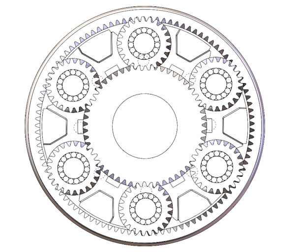
Six-Planet Gearset
On that subject, a big problem we have seen when trying to use automotive planetary hardware in a PSRU is the fact that the needle bearings inside the planet gears often do not have an acceptable life under the applied loads. We require a 95% probability of at least 2000 hours of life for rolling element bearings. We do not consider 200 hours (or even 500 hours) acceptable. (For a detailed presentation on the determination of the life of rolling element bearings, CLICK HERE.)
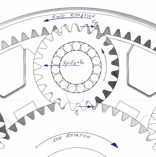
The following picture (carrier-fixed application, with either sun-driving or ring-driving) shows the torque-generated forces that are applied to the planet bearings. The load applied to mating gear teeth is the applied torque (lb-in) ÷ the pitch radius of the driving gear (in). As shown in the diagram, the load applied to the planets by the driver is equal and in the same driection as the force applied to the planet by the driven gear, so the opposite-and-equal force that the planet axle applies to the bearings is 2 x the force applied by the driver.
If the sun gear is the driver, then the tooth forces are high because of the small pitch radius of the sun gear, whereas if the ring gear is the driver, the mating gear tooth forces for the same input torque are much smaller, due to the large pitch radius of the ring gear.
Here is an example.
Suppose we designed a PSRU that used a 6-planet Ford E4OD / 4R100 front planetary gearset (the most robust of the planetaries from that gearbox) for an engine producing 300 hp at 6000 RPM.
The three available step-down ratios with the E4-OD front planetary gearset are:
- 1.538 (Ring-driving, Sun-fixed, Carrier-out, same direction),
Ratio equation: 1 + sun tooth count ÷ ring tooth count - 1.857 (Sun-driving, Carrier-fixed, Ring-out, reverse direction),
Ratio equation: - ring tooth count ÷ sun tooth count - 2.857 (Sun-driving, Ring-fixed, Carrier-out, same direction).
Ratio equation: 1 + ring tooth count ÷ sun tooth count
At 6000 input RPM, a 300 HP engine applies a mean torque of 263 lb-ft to the gearbox input shaft.
If we select configuration 2 (Sun-driving, Carrier fixed, Ring-out, 1.857 ratio, reversed rotation), with an input speed of 6000 rpm, the planets spin at 14000 rpm. The pitch diameter of the sun gear in that set is 2.377, so the pitch radius is 1.188 inch.
At 263 lb-ft of input torque, the total tooth load from the torque is 2656 pounds (263 x 12 ÷ 1.188), so the load applied to each set of planet-gear needle bearings is 885 (2 x 2656 ÷ 6) pounds, assuming exactly equal load sharing among the 6 planet gears { which rarely occurs }.
However, assuming equal load-sharing and suitable bearing lubrication with filtered oil having a viscosity of 20 centistokes, the life prediction analysis shows that under those load, speed and lubrication conditions, the probability is that 99% of those bearings will survive for 122 hours of operation, the probability drops to 95% that the bearings will survive 355 hours, and it drops to 90% that they will survive 582 hours.
Now we fully understand that it is highly unlikely that this hypothetical PSRU would be exposed to the full engine torque and speed for 300 hours during the life of the typical experimental aircraft (see the discussion of LOAD MODELS). However, the usefulness of a 1.857 ratio with reversed rotaion on a 6000 rpm engine seems a bit limited. With that ratio, the engine at 6000 RPM would produce a propeller RPM of 3231. To get a propeller RPM of 2700, the max engine speed would be limited to 5014, which would put a serious dent in the max engine power available.
Added to that, there are enough other variables in predicting a design life for this gearset to make it look like a marginal design. To my way of thinking, a 10% probability of gearbox bearing failure in 582 hours is not suitable for an aircraft application.
With the two remaining configurations (1 and 3), the carrier is not fixed. Regarding any configuration in which the carrier is spinning, there is an additional load on the planet bearings, generated by the centrifugal load of the planet gears whirling about the sun gear. That centrifugal force generates an additional bearing load applied perpendicular to the torque loads, and it vector sums with the torque-generated load to produce an even larger load on the planet bearings.
In configuration 3 above, (Sun-driving, Ring-fixed, Carrier-out, 2.857 ratio, same direction), the bearing load from the applied torque is still 885 pounds at the same input conditions. However, the carrier RPM is 2100, so the planet gears produce an added centrifugal load of 47 pounds. But because the planet speed drops to 7000 RPM (for 6000 input), the predicted life for 99% survival increases to 245 hours. That is better, and the application of Load Model analysis to this scenario suggests that a safe 2.857 ratio PSRU could be designed from the E4OD 6-pinion front planetary for applications with less than about 275 lb-ft of peak torque. The life of the components would require a very effective coupling system that eliminates almot all of the torsional peaks the engine generates (see Torsional Output of Piston Engines).
With regard to configuration 1 above (Ring-driving, Sun-fixed, Carrier-out, 1.538 ratio, same direction), the planet-gear speed (with the same 300 HP, 6000 RPM input) is 13,000 RPM, but the torque-generated planet-bearing load drops to 477 pounds because the pitch diameter of the ring gear is 4.414, (pitch radius = 2.207), so the applied tooth load falls to 1421 pounds (263 x 12 ÷ 2.207) and the planet bearing load in that case(spread over 6 planet gears) is 2 x 1421 ÷ 6 = 477 pounds. Because the carrier is rotating at 3900 RPM, the centrifugal load generated by each planet gear is 161 pounds, which resolves to a total bearing load of 503 pounds. Under those conditions, the predicted survival life of 99% of the planet bearings is 843 hours, but the 95% predicted survival jumps to 2450 hours. Quite a difference. That sort of bearing life prediction is acceptable, but the 1.528 ratio with a 6000 rpm engine seems not very useful. Outside the Reno Air Races, there are not many (conventional airplane) propellers (never mind ducted fans, 12000 rpm model plane props, etc.) that can withstand 3900 RPM, much less provide any useful performance at that speed.
(As an aside, the centrifugal loads can be extremely high, depending on the planet gear weight, the planet gear pitch circle diameter and he carrier rpm. In one custom-designed planetary system we did for a very high speed application, the planet gears generated nearly 4000 pounds of centrifugal load, which was actually twice as large as the torque-generated load.)
Then there is the additional problem with using automotive planetary gearsets. Most of them are implemented using helical gears with fairly large helix angles, resulting in substantial gear thrust loads. The thrust loads on the planet gears are resisted by flat thrust washers between the gear faces and the mating carrier faces. The problem is that there is not a sufficient supply of lube oil to the faces of these washers to adequately lubricate or cool them under the sustained application of high input torque.
In fact, experience has shown with several of the PSRU's based on automotive planetary gearsets, that the thrust washers go away even before the planet bearings start to fail. That lack of lubrication affects the planet bearing survival as well, and significantly reduces it below what is predicted assuming adequate lubrication (as described above).
We have looked at some of the high-capacity 6-pinion gearsets from various truck transmissions. Those offer the prospect for higher capacity reduction gearboxes in the Sun-Driving, Ring-Fixed configuration. But, as with any off-the-shelf gearset, one must be satisfied with the ratio that it provides. We recently designed a clean-sheet helicopter gearbox using just such a heavy-duty 6-planet system from a burly truck transmission. It was adequate (by aircraft standards) for a 200 HP turbine engine. However, it would not be suitable for a 300 HP piston engine without some serious modifications.
When adapting automotive hardware to aircraft use, you must keep in mind the automotive load model vs. the aircraft load model. (For more information on Load Models, CLICK HERE).
The planetary applications we have observed appear to be following a design philosophy which implements a very high first and second mode torsional resonant frequency. As you will see in the section on torsional vibration, that approach works against the implementation of a light, long-life gearbox, and can be devastating to a propeller. (More information on potential prop problems appears in the PROPELLER VIBRATION ISSUES section.) Further, the absence of the design and manufacturing details necessary to achieve actual (as opposed to theoretical) load sharing among the planet gears can cause much higher loads to applied to certain parts than were anticipated in the design.
OFFSET GEAR DRIVES
The next configuration to consider is the offset (helical and straight) gear reduction (such as used on the Continental GTSIO-520 / 550, the Rolls-Royce Merlin and the Allison V-1710 engines) in which the centerline of the propshaft is offset (usually upward) from the centerline of the engine crankshaft.
If the design includes an internally-toothed driven gear, it immediately suffers from the engineering deficiency of having a heavily loaded shaft (propshaft) in an overhung configuration. (Allison tried that approach in their early V-12’s and abandoned it.)
For the decision whether to use helical or spur gears, the issues include:
- noise (helicals are quieter, but who can tell in an aircraft?),
- the additional cost for helical gears having the necessary American Gear Manufacturers Association (AGMA) quality level,
- asymmetric tooth loading (edge-loading) on helical tooth pairs which are in partial contact (contact across only a part of their face width), and
- the necessity for a helical design to include suitable bearings (ideally not washers) to absorb the considerable thrust loads generated by helical gears.
The issue of thrust absorption is non-trivial. The output shaft provides for propeller thrust absorption anyhow, but the design must accommodate significant thrust loads on the input shaft, as well as any intermediate (idler) shafting. Solidly attaching the input shaft to the back of the crankshaft in order to use the engine thrust bearings is generally a poor solution, for two reasons:
- the crankshaft does NOT operate concentric to the bearing centers, so the connection must be designed so as not to constrain the radial movement of the crankshaft, and
- it can be difficult to make the rigid connection have the torsional rate necessary to achieve isolation from the engine torsional excitation (covered later in great detail).
On the positive side, helical gears do have a significantly greater contact ratio than spur gears of similar diameter and tooth pitch. Helical gears are also much quieter than spur gears, but in an aircraft application, who can tell the difference?
For reasons of reliability, simplicity and cost, EPI chose externally-toothed spur gears for it's geared PSRU. See the GEAR DESIGN section for a full presentation on the superiority of spur gears.
NOTE:
I have recently added a page to this site that describes the COMPLETE DESIGN PROCESS that I use for a PSRU (and for other gearbox applications as well).
