- Mark-25 -
Turbine Helicopter Power Transmission System
COMPLETE - From the Turbine Engine to the Main & Tail Rotors
NOTE: All our Products, Designs, and Services are SUSTAINABLE, ORGANIC, GLUTEN-FREE, CONTAIN NO GMO's, and will not upset anyone's precious FEELINGS or delicate SENSIBILITIES.
INTRODUCTION
In mid-2016, the CEO of a German aviation company contacted EPI to inquire about our interest in designing a complete power transmission system for the new 2-place turbine-powered helicopter his company was developing.
After our initial conversations, the CEO flew to the US to have a meeting with us to discuss the requirements and philosophies of such a design.
After a 3-hour meeting, he awarded EPI a contract to design his power transmission system, and work began immediately on this exciting project.
The result (the EPI Mark-25) is a system that meets or exceeds the requirements, is robust, is economical to produce, is lightweight, and is simple.
The prototype of the helicopter, complete with our Mark-25 power transmission system, was on display at Aero-Friedrichshafen-2019 (the Eurpoean "Oshkosh"). Here are two pictures of the helicopter from that show.

New Helicopter at Friedrichshafen - Starboard Side View
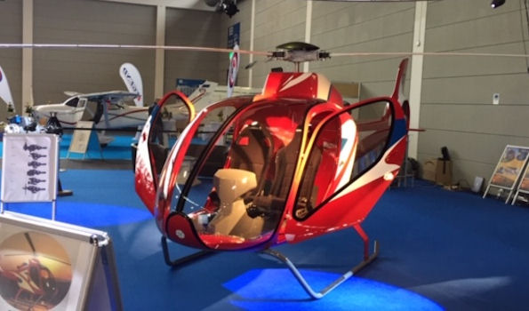
New Helicopter at Friedrichshafen - Port Side View
The following two pictures show the prototype helicopter parked in the plaza outside the client company's headquarters.

New Helicopter at Home - Overhead View

New Helicopter at Home - Front View
CLICK HERE
for a quick video of this prototype helicopter on display at Aero-Friedrichshafen-2019, showing the EPI Mark-25 transmission system (timestamp 1:37).
CLICK HERE
for a video of one of the early test flights of this new helicopter.
CLICK HERE
for a video of a test flight of the completed helicopter.
ENGINE DETAILS
The client company developed a new, 185 hp turbine engine for this new helicopter. The new engine has a single-stage radial-flow compressor and a single stage radial-flow turbine. The design is based loosely on the old allegedly-160 hp Solar-T-62.
However, this new engine has, by the redesign of the compressor and turbine wheels using contemporary radial flow compressor and turbine wheel technology, and by the optimization of the compressor diffuser, the combustor section, and the turbine nozzle, achieved a steady sea-level 185 hp, along with some impressive (unpublished as of yet) BSFC numbers.
The use of contemporary metallurgical technology enables this engine to operate reliably at elevated turbine inlet temperatures. The use of a custom-developed ECU that uses sophisticated control algorithms allows the engine to operate much closer to the compressor surge limits and to the turbine maximum inlet gas temperatures, which are substantially higher than the old T-62 numbers.
The company manufactures this new turbine engine, taking full advantage of sophisticated 5-axis CNC techniques and refined CMM equipment and QC procedures, assuring the very close tolerances that provide consistency of operation from engine to engine.
The new engine-with-transmission system has been undergoing extensive dynamometer testing and is accumulating the test hours to achieve the European Certification required to be allowed to fly.
The following two pictures show the new engine and the EPI accessory drive, partially crated for shipment.
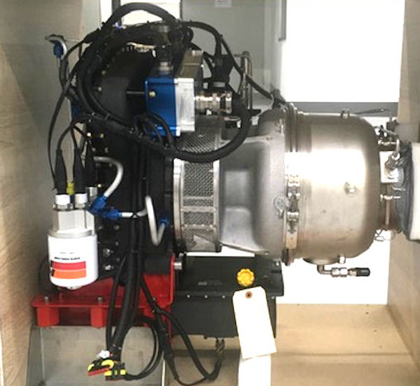
Engine, Control Module, and Accessory Drive - Port Side View
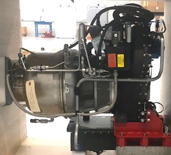
Engine and Accessory Drive - Starboard Side View
POWERPLANT SYSTEM
The following picture shows the complete transmission system, with the 185 hp turbine engine installed.
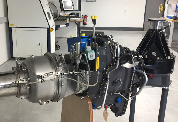
Complete Mark-25 Power Transmission System - with Engine
For this project, EPI produced and delivered to the client the following items:
- the complete transmission system design in 3D-CAD, consisting of individual part models and working assembly models,
- complete assembly drawings and parts lists,
- many of the critical manufacturing drawings and process sheets,
- a 33-page analysis document detailing the loads and calculated lives of all the major components (gears, shafts, bearings),
- a 125-page fully illustrated assembly instruction manual, and
- the first five prototypes of the Lubrication and Control module.
The client company and its subsidiaries make all the transmission manufactured components (housings in both aluminum and magnesium, first stage gearing, accessory drive gearing, all shafts, plumbing, etc). The company purchases the other components from well-known suppliers of high quality parts and accessories. The company performs all the QC inspections and processes in-house, then assembles and tests the complete transmission system.
The EPI M-25 power transmission system consists of the following elements:.
- The first-stage planetary gearset that reduces the 62,000 rpm output of the turbine engine to 6089 rpm;
- A geared accessory drive section that couples to the 6089-rpm first stage output gear, and contains the starter system, a high-output alternator, and the main oil pump that provides pressure-lubrication to all the components as well as actuating pressure for the hydraulic clutch;
- The second-stage planetary gearset that reduces the 6089 rpm first-stage output to 2147 rpm;
- A multi-disc hydraulic clutch which allows the engine to start and spool up to ground idle with a minimum amount of load engaged;
- A very-high capacity sprag clutch that serves as the autorotation clutch as well as an automatic disconnect from the rotor system in case of an engine or gearbox failure;
- A step-up Hy-Vo chain drive to provide the tailrotor (ducted fan) system with a 4736 rpm driveshaft output;
- A secondary oil pump, driven by the output of the autorotation clutch, which provides backup lubrication and hydraulic pressure in case of a problem with the main oil pump or gearbox, and during autorotations when the engine speed is low (or zero);
- A high capacity, 90° final drive gearset that reduces the 2147 input rpm to 520 main rotor rpm;
- A high-capacity pressure-lubricated final drive bearing and support system to transfer all the main rotor loads into the airframe;
- A lubrication and hydraulic control unit that - (a) provides full-flow filtering of the gearbox system lube oil, - (b) controls system oil temperature, and - (c) uses binary and proportional solenoid valves and custom orifices to control the engagement and disengagement of the hydraulic clutch;
- A separate final-drive lubrication system for the special gear oil that is required for those gears, which includes a separate, independent lube oil pump, filter, chip detector, temperature sensor, and cooler;
- A suitable mounting system that properly attaches the whole powertrain to the airframe, and allows for the airframe distortions that occur under various flight loads.
FIRST STAGE REDUCTION
The first stage reduction gearing is a 3-planet gearset in the sun-driving / carrier-fixed / ring out configuration. It is fundamentally a redesign of the old T-62 first stage gearing. It uses the same concepts, the same gear tooth forms, and the same tooth counts as the original T-62 system, but provides metallurgical and design improvements which increase the torque capacity and eliminate the weaknesses and wear issues from the original T-62 design.
This improved gearset can be used as a direct bolt-in replacement for the first-stage gearset in existing T-62 engines. The system is available from EPI, which imports the components from the client company.
In this gearset, the planet gears are fixed in place by the carrier, and both the sun gear and the ring gear are free to float radially so as to provide nearly perfect load sharing.
In place of the old T-62 cast aluminum carrier, the new planet carrier is fully CNC-machined from a billet of high-strength aluminum alloy.
All the gears provide increased capacity and life by means of improved metallurgy and heat-treatment as well as increased contact surface area. The planet gear bearings have much greater load capacity, accomplished by (a) the use of larger bearings having substantially more capacity than the original T-62 ball bearings, and (b) by the use of components that preload the bearings to eliminate the ball-race slippage issue that occurs in non-preloaded high speed rolling element bearings.
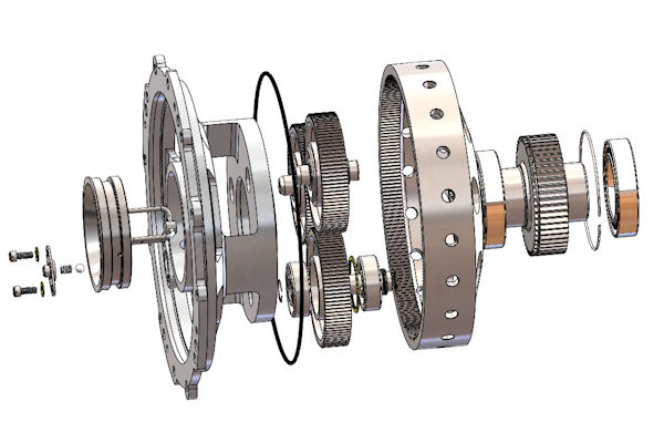
Stage 1 Reduction
ACCESSORY DRIVE SECTION
The accessory drive section is geared to the output of the first stage planetary. It provides the drives for the lightweight, 80-amp alternator and the 100-psi system main oil pump. It also provides the interface for the lightweight, 2.7 hp starter motor.
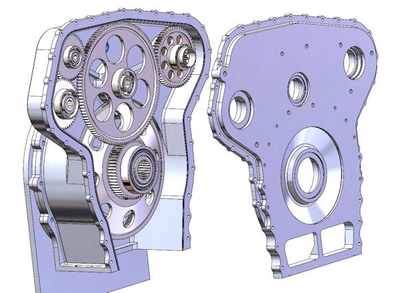
Accessory Drive
SECOND STAGE REDUCTION
The second stage gearset is a heavy-duty six planet system in the sun-driving / ring-fixed / carrier-out configuration that provides a 2.836 ratio, and is driven by the internal spline in the first stage output gear. This reduction is a modified version of a production gearset taken from a high-capacity diesel truck transmission. As such, the gears, the carrier, the planet gear shafts, and the planet gear bearings ( which are the usual weak link in a sun-driving planetary gearset ) are very robust.
Stage 2 Reduction
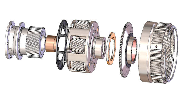
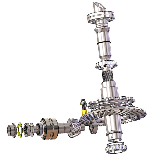
STARTUP and AUTOROTATION CLUTCHES
The purpose of the startup clutch is to remove all possible load from the engine during startup so that the turbine engine can spool up to start rpm quickly, then accelerate as quickly as possible to ground-idle, where the airflow is sufficient to keep from overheating the turbine section. Failure to achieve a steady-state ground idle condition in a very short time can irrecoverably damage the turbine section (a "hot start"). The engine ECU monitors the startup conditions, and chops the fuel flow if the transient startup parameters indicate a hot start may be imminent..
The input to the startup clutch is the output from the second stage reduction gearset. This clutch is a hydraulically-engaged multi-disc oil-cooled clutch system, based on components of a clutch used in a high-capacity commercial diesel truck transmission.
The autorotation clutch is a high-capacity sprag unit that is integrated into the driven component of the startup clutch. The purpose of the auto-clutch is to instantaneously and automatically disconnect the rotor system (main and tail rotors) from the power system whenever the input speed to the autorotation clutch is less than the speed of the output race of that clutch (the speed of the rotor system drive).
That allows the pilot of the aircraft to maintain rotor system rpm during a descent without requiring that engine power is available. That piloting skill translates the potential energy of the helicopter (altitude) into kinetic energy that is stored in the rotor system. Properly executed, that stored kinetic energy is sufficient to allow a controlled-arrest of the helicopter's descent just before ground contact (an "autorotation").
If the engine speed is restored to the point where the input speed of the autorotation clutch matches the output speed (rotor system speed), the sprag automatically and smoothly re-engages, restoring engine power to the rotor system.
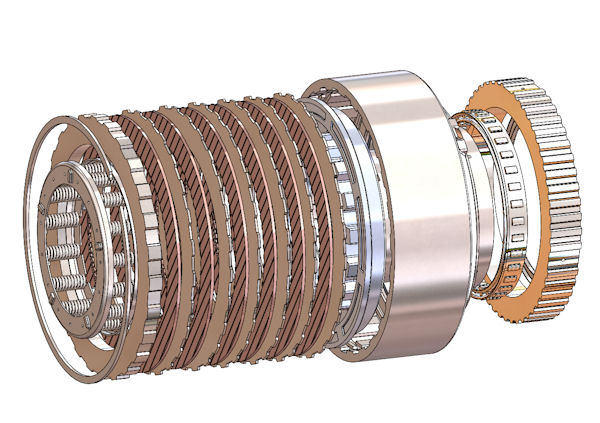
Startup and Autorotation Clutch System
ROTOR SYSTEM DRIVE
The outer race of the autorotation clutch drives:
- the input to the main rotor 90° gearing,
- the step-up drive for the tailrotor ducted fan system, and
- the secondary gearbox system oil pump, which provides lubrication and hydraulic pressure in the absence of sufficient output from the main oil pump.
MAIN ROTOR FINAL DRIVE
The main rotor final drive is a custom-designed 90° spiral-bevel gear system in which the driven gear is mounted above the driver in order that any debris that might enter the system is far less likely to jam the final drive gearset.
This drive uses a high-capacity gearset from an application rated (by the manufacturer) at 800 hp. As explained HERE, the power a gearset can transmit is a dependent variable, determined by (a) the input torque capacity of the gears and (b) the RPM at which they are operated at a given input torque. The meaningful rating is that these gears can provide "infinite life" at an input level of 400 lb-ft of torque. Both gears are extreme-quality, matched-set productions having precision tooth forms, proprietary heat-treatment, shotpeened after heat-treat, then isotropic-superfinished (ISF).
The driving gear is supported on the outside of the gear by a large, opposed-double-tapered roller bearing, and on the inside (behind the gear) by a large cylindrical roller bearing. That design assures the absence of overhung or cantilevered loads on the driving gear.
The driven gear is attached to a custom-designed, high-strength spool that is supported in high-capacity tapered roller bearings. There is a lubricated support mechanism on the driven gear directly behind the mesh with the driving gear. That mechanism prevents gear separation loads from deflecting the driven gear away from the driver.
The custom spool is necessary in order to provide the load capacity required by the main rotor drive spline in order to transmit up to 1550 lb-ft of torque to the main rotor shaft.
The housing system is a custom design that provides (a) rigid support for the gearing, (b) rigid support for the main rotor radial and thrust loads, and rigid support for part of the mounting system that attaches the powertrain to the airframe.
The final drive uses a separate lubrication / cooling oil system, including a dedicated pump, filter, chip detector and temperature sensor, so that the special oil required for this type of gearing can be used.
Later in the program, a test session is planned to determine whether the final drive can operate successfully on the same oil as is used in the gearbox. If that proves successful, the dedicated final drive pump can be eliminated, as well as the several sealing components that keep the two oil systems segregated.
Main Rotor Drive
TAILROTOR SYSTEM DRIVE
The tailrotor system is a ducted fan which requires a fairly high drive rpm. The gearbox provides a 2.206 ratio step-up drive that supplies a 4736 rpm tailrotor shaft output speed.. That drive uses a high-capacity Hy-Vo chain system so as to eliminate the cost of several gears that would otherwise be needed to provide the axial offset distance required by the airframe and the tailrotor drive system
LUBRICATION and HYDRAULIC SYSTEM
The gearbox oil system contains two pressure pumps: the main pump, driven by the engine, and the secondary pump, driven by the output of the autorotation clutch. System pressure is regulated at 100 psi by the regulator valve integrated into the main oil pump.
Each pump draws from a dedicated supply port. Those ports are positioned and oriented so that the flow of oil will not be interrupted by extreme maneuvering or "g" loading.
The output of both pumps flows into a common port in the Lube and Hydraulic Module, where it all flows through a 10-micron high-flow filter that has a 12 psi differential bypass valve, then into the oil thermostat cavity.
When the oil temperature is below the thermostat activation point, the thermostat control valve is fully open, thus providing equal pressure at the inlet and outlet of the airframe-mounted oil heat exchanger, so all the oil flows into the lube outlet chamber.
As the oil temperature rises above the thermostat activation point, the valve begins to close, causing a certain amount of the oil to flow through the heat exchanger, then back to the lube outlet chamber. When the valve is fully closed, all the oil passes through the HX before going to lube outlet chamber.
The lube outlet chamber provides pressurized oil to the turbine engine, to all the bearings, bushings and gears, in the gearbox. The lube oil then drains back into the deep sump.
In addition to the lubrication functions just described, this Lube and Control Module also implements the mechanism by which the ECU controls the gearbox startup clutch.
A small orifice feeds oil pump pressure from the thermostat inlet cavity to a pair of solenoids that are aranged so as to control the startup clutch engagement pressure. During engine start, the solenoids are activated in a way that assures no oil pressure is applied to the clutch, so that the clutch is fully disengaged by the internal springs.
When the engine reaches an rpm at which it can successfully pick up the rotor system load, the ECU manages the solenoids so as to apply an increasing level of hydraulic pressure to the clutch in order to accelerate the rotor system at the maximum permissible rate, so as to minimize clutch slippage.
If electrical power is lost, or if there is a failure or one or both of the solenoids, the control module defaults to provide full hydraulic pressure to the clutch. Therefore, full clutch engagement is the fail-safe mode.
When the pilot selects the rotor shutdown function, the ECU signals the Lube and Hydraulic Module to remove clutch pressure, and the clutch disengages, allowing the rotor system to coast to a stop.
There are three oil pressure sensors in the module that allow the ECU to monitor the inlet and outlet pressure across the oil filter, as well as the value of the clutch engagement pressure.
The following two pictures show the Lube and Hydraulic module.
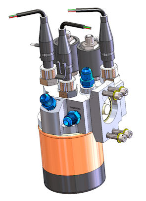
Lube Module-Left View |
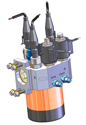
Lube Module-Right View |
This completes the description of the EPI Mark-25 helicopter gearbox.
