- The Basics of Valvetrain Technology, Part 2 -
An In-Depth Discussion of Valvetrain Components
NOTE: All our Products, Designs and Services are ORGANIC, GLUTEN-FREE, CONTAIN NO GMO's, and will not upset anyone's precious FEELINGS
INTRODUCTION
1. This series of two articles (Part 1 and Part 2) is intended to be an introduction to the fundamentals of valvetrain technology. For a deeper dive into the vast engineering details of this subject, I strongly reccomend this magnificent book. It is authored by Dr. Billy Godbold, nuclear physicist, former chief engineer at Comp Cams, and currently operating his own consulting business, Godbold Engineering Solutions. Dr. Godbold is highly-sought-after by many of the giants in today's racing world.
2. This series of two articles is primarily focused on pushrod-type overhead valve (OHV) engines. The same principles apply to other types of camshaft-operated valvetrains (SOHC, DOHC, etc) with the exception of discussions involving pushrods.
3. Although many "experts" sneer at pushrod-OHV engines as being "archaic" (I heard one eurosnob refer to them as "agricultural"), the fact is that pushrod overhead valve engines are simpler and more compact when compared to other alternatives. From the crankshaft to the top of the cam cover, a pushrod OHV engine is shorter and narrower than an OCH engine of comparable layout and displacement. (For example, compare the compact, clean GM-LS engine line to the morbidly-obese Ford "modular" SOHC and DOHC engines.). GM is a huge company, with resources to match, and has a lot of clever engineers. When GM looked at new engines to replace the old SBC / BBC, they studied the available options and concluded that a compact pushrod V8 was what they needed.
4. And the fantasy that a DOHC layout is required for the best power output is convincingly put to rest when one considers the cam-in-block, pushrod, 2-valves- per-cylinder, single-4-barrel-carburetor engine used in NASCAR CUP until the end of the 2014 season, that produced over 890 HP at 9000 RPM.
BACKGROUND
Preparing an engine to achieve maximum performance is an exercise in system engineering. It requires careful consideration in parts selection, machining and assembly. There are dozens of components that must work in harmony to produce the most efficient cylinder filling, most efficient combustion, most efficient cylinder exhausting, and the minimization of heat losses and frictional losses, so as to deliver maximum thrust on the pistons across the duration of the combustion cycle.
When one contemplates power increases, typically the first thoughts are about the induction system. However, in order to reap the maximum benefits of optimized head porting and manifolding combinations, or from forced induction, the valvetrain must be up to the task.
Whenever moving to a bigger cam and / or higher RPM, special consideration must be given to the lifters, pushrods, rocker arms, valve springs, retainers, and keepers. If the valvetrain is operating in an uncontrolled manner (meaning you have valve float or bounce, spring oscillation, pushrod deflection, etc), performance AND reliability will suffer.
Additionally, poor parts selection or improper setup can rob power and / or lead to a costly and catastrophic failure. It’s hard to be consistent or win races when your engine encounters valve float, broken valvesprings, dropped valves, or valve-to-piston contact. The key, then, is to configure a SYSTEM of well-matched, high-quality parts that is appropriate for your application.
CAM DESIGN
In the beginning, cam lobe profiles were designed by engineers using French Curves and drafting tables to produce what seemed to be smooth lift profiles. However, when the dynamics of those eyeball profiles proved to be less than desirable, some enterprising soul decided to differentiate those lobe-lift profiles and discovered that the resulting velocity profiles were far from desirable. Taking that one step further, and differentiating the velocity profiles produced some downright scary acceleration profiles.
To remedy this massive design deficiency, in the mid-1950's, Harvey Crane devised the notion that a better way to get a good lobe is to begin with a good acceleration profile, then integrate back to the resulting velocity profile, then integrate that back to the resulting lift profile. Using the resultant lobe lift profile and the geometric properties of the components, it is straightforward to generate cam lobe dimensions that produce the targeted lift profile.
The geometric properties mentioned include: the maximum radius available for the lobe peak {established by the ID of the camshaft bearings}, the minimum base circle that the camshaft in question can support, and cam follower dimensions and properties - { flat, roller, radiused }.
That was the accepted procedure for two or three decades, until researchers arrived at the conclusion that lifter motion was not really the intended target, because all the components in the OHV (or ANY) valvetrain have effective spring rates; that is, they deflect a predictable amount as a function of the applied load. And remember, the load applied to a component is the product of the mass of the component times the acceleration imposed on that component. Another interesting fact is that the masses on the valve side of the rocker arm transfer over to the lifter side by the rocker ratio squared.
So the real target is valve motion, which is different from lifter motion because of several factors, including (but not liited to): camshaft bending deflection; camshaft torsional deflection, pushrod deflection {both compressive and Euler column deflection}; rocker arm deflection, rocker arm mounting system deflection, and valvestem compressive deflection. And all those deflections have individual resonant frequencies and damping factors.
So contemporary cam lobe design begins with a desired valve motion profile.
Trent Goodwin, an engineer at Comp Cams, says: “We are far more concerned with valve motion than anything on the cam and lifter side. Those components (cam, lter, pushrod) are developed under some geometric constraints to produce the desired motion of the valve, and never the other way around. We really do not design ‘camshaft profiles'. That was the way things were done in the 1970s and ’80s, but from the late 1990s through today we always start by designing valve motion. After you develop the lift, velocity, acceleration, and jerk curves you want for an application, then you work backwards though the rocker arm, to the pushrod, and back to the required tappet motion to produce that valve motion. Knowing the required tappet motion, the cam profile is calculated using the theory of envelopes to determine the requisite cam surface. Beginning with desired valve motion design, the role of the lifter becomes clear. You are calculating a lifter position at every cam degree that is required to convert the linear position of the valve from its rest on the seat to the angular position of the camshaft as it is driven at half crank speed. In mathematics and physics, this relationship is known as a coordinate transformation and often solved with Laplace Transforms.”
SPINTRON™ machines, coupled with high speed photography, laser-tracing, and other high-tech recording systems have enabled valvetrain manufacturers to characterize valvetrain performance deficiencies in excruciating detail. Those capabilities, coupled with improved metallurgy, manufacturing, and QC have provided the capabilities to produce stable pushrod valvetrains that can run in excess of 10,000 RPM.
To get a visual perspective on some of the dynamics and uncontrolled motions that exist in a valvetrain, click on the picture below to watch a very interesting video. It is from a high-speed photography study of valvetrain motion at 9000 RPM done by a well-known NASCAR engine manufacturer, showing the startling amount of bending and vibrating motion, and ultimately a torsional failure of the valvespring. You can see the development of the helical fracture line in the second coil up from the bottom, and you can see flakes of material begin to shed from the fracture line. Also note the surprising amount of motion at the valvestem tip and the spring vibration that occurs after the valve closes.
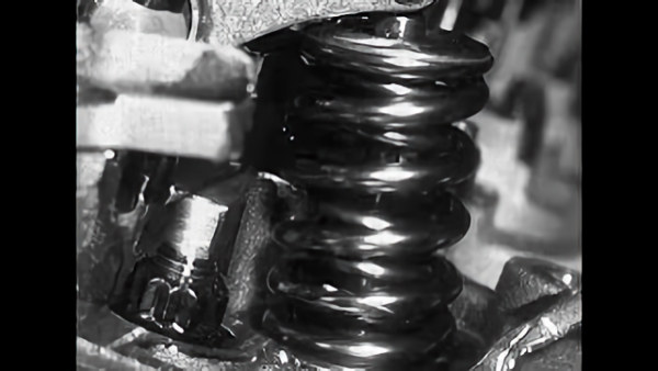
Link to a Video of Valvespring Motion and Failure
Valvetrain Operation - and Problems
The purpose of the valvetrain, of course, is to convert the spinning motion of the camshaft to the up-and-down action of the valves. In a typical cam-in-block, overhead valve engine, the valvetrain consists of the camshaft, lifters, pushrods, rocker arms, valve springs, valve spring retainers, retainer locks, and of course, the valves.
It is the desire of any engine builder to have the valves open and close when directed to — but that doesn’t always happen. Aggressive cams can cause the lifters to separate from the lobe surface ("loft"), and the valves to travel past the desired lift point. Meanwhile, deflection in the pushrod and rocker arm can prevent maximum lift from being achieved, and weak springs can cause float or bounce.
Just because the valvetrain components are designed for severe duty doesn’t ensure they’ll work as desired. Keeping the valvetrain operating properly is not an easy task (as demonstrated by the video above), and often, things that would normally make a valvetrain run smoother can actually have the opposite effect.
The motion of the valvetrain begins when the cam lobe starts to move the cam follower ("lifter"). Lifters ride directly on the cam lobes and transfer the lifting motion to the pushrods. Actual valve lift and duration are dictated by the shape of the lobe, the rocker ratio, the stiffnesses of the lifter, pushrod, rocker arm, and the valvespring characteristics.
The pushrod, when acted upon by the lifter, raises one side of the rocker arm, and much like a see-saw, the opposite side of the rocker travels downward to open the valve. Once the lobe acceleration profile has entered the negative acceleration portion of the profile (at the point of maximum opening and closing velocity, as explained in PART 1), the valvespring(s) provides the force necessary to decelerate the valvetrain to zero velocity (at peak lift, "over the nose"), then to accelerate it back toward closing, ideally keeping the lifter in contact with the cam lobe. When the acceleration profile crosses back into the positive region (at maximum closing velocity), the cam lobe then exerts the deceleration force on the valvetrain to move the valve back onto its seat.
In order to feed the engine maximum airflow, it is common to increase not only the lift and duration, but also the speed at which the valves open and close. Steeper ramps on the lobe snap the valvetrain into action. This rapid change in the lobe / lifter acceleration profile (third derivative, termed "jerk") produces impact loads on the valvetrain that can be destructive. Sometimes increased spring load and spring rate are strategies used to counteract this effect, but that too causes additional loading on the camshaft, lifter, pushrod, rocker arm, valvespring(s) and valve.
To prevent failures, the aftermarket has developed more robust lifters, pushrods, rocker arms, springs, retainers, and valves, all of which utilize stronger materials and better designs, and ones that are larger in scale as compared to factory components.
Lifter Types
There are four basic types of cam followers (lifters, tappets) in pushrod engines:
- Solid-Flat
- Hydraulic-Flat
- Solid-Roller
- Hydraulic-Roller
The fundamental differences are evident from the four names.
"Flat" or "roller" refers to the interface between the cam lobe and the lifter base.
Flat lifters provide a sliding interface to the cam lobe. ("FLAT" lifters are not really flat - the "flat" surface is really a sphere having a 50 to 60 inch-radius, which interacts with the slightly-tapered and slightly-off-lifter-center cam lobe to promote lifter rotation.)
Roller lifters implement a wheel ("roller") that theoretically provides a rolling interface (hertzian stress only) to the cam lobe instead of a sliding interface. The roller is riding on either either needle bearings or bushings, which are riding on the roller axle fixed into the end of the lifter.
Hydraulic lifters use an internal hydraulic piston mechanism that automatically adjusts valve lash during engine operation, to compensate for differential expansion of the engine components as engine temperatures change.
Solid lifters are, as the name implies, rigid, and require some external method for setting lash: adjustable rocker arms, adjustable pushrods, adjustable lifters (as in the old Ford Flathead engines).
One manufacturer claims to have implemented previously-unheard-of tolerances (+/-0.0002) in their lifter manufacturing processes. (Others likely have the same tolerance capabilities.) Other lifter options include REM finishes with DLC coatings.
The aftermarket products use exotic metallurgy, proprietary heat-treat processes, and discriminating, in-house quality control procedures.
Admittedly, aftermarket valvetrain components tend to be pricey, BUT you only have to ruin one $100,000 engine to realize the value in quality componentry.
Solid-Flat / Solid-Roller Lifter Types
As the name implies, a solid lifter is one solid cylindrical unit with either an “apparently” flat surface or a roller wheel on the bottom which rides on the cam lobe, and has a cup on the opposite side to capture the pushrod.
Solid lifters require valve lash to compensate for thermal expansion of the parts. This adjustment is normally made using a feeler gauge between the rocker and the valve tip. While solid lifters have the potential to produce more power than hydraulic lifters (by allowing higher RPM before lofting), they can be noisy and they do require regular adjustment.
Basic solid flat-tappets are inexpensive, but there are drawbacks. Most flat-tappet cams require a specialized break-in oil and routine, require engine oil that has been fortified with the anti-wear compound Zinc Diethyl DithioPhosphate (ZDDP), and you’ll be limited on lifter maximum velocity because the instantaneous radius on the cam lobe must remain tangent to the lifter face, and therefore is limited by the diameter of the lifter. Too aggressive, and the lobe surface will run off the edge of the lifter.
The cam lobe will run off the edge of an 0.842 diameter flat tappet at around 0.007-inch-tappet-lift-per-degree, whereas an 0.875 tappet diameter will allow about 0.0073 inches-per-degree, and an 0.900 diameter tappet can handlle about 0.0076 inches-per-degree.
The answer is a solid roller lifter, which incorporates a roller wheel at the bottom. The roller rides directly on the camshaft, reducing friction and allowing much more aggressive lobe profiles. Most of today’s V8 engines come with hydraulic roller lifters, as they allow the more aggressive profiles of a roller cam, allowing quicker opening and closing rates, with low maintenance.
Hydraulic-Flat / Hydraulic-Roller Lifter Types
Hydraulic lifters take up the slack or lash in the valvetrain and can compensate for thermal expansion of the parts whether the engine is cold or at operating temperature. These lifters use a cushion of oil to take the slack out of the valvetrain, eliminating the need for constant adjustment, and they can absorb, to a certain degree, impact loads in the valvetrain, which helps in overall reliability in service.
While solid lifters offer simplicity, great performance, and a reputation for being more “racy,” today’s hydraulic lifters can offer amazing performance, with less maintenance. Hydraulic lifters have been used by OE manufacturers for decades, even in many factory high-performance applications.
Hydraulic lifters are made up from a hollow steel cylinder with an internal piston that’s retained by a strong clip. Pressurized oil is fed to the lifter through an orifice in the lifter body. When the lifter is on the base circle of the cam, the lifter is free to fill with oil. But when the cam lobe begins to move the lifter, an internal check valve closes off the oil port and traps the oil inside between the lifter and the piston. Because oil is virtually incompressible, the lifter acts as a solid component until the cam lobe releases its pressure on the lifter.
The hydraulic roller lifter is now used in almost all OE pushrod engines. They have proven their durability and effectiveness in these applications, and when used properly in racing applications, they can be just as durable and efficient.
Is there a performance advantage between hydraulic and solid lifters?
Again, quoting Trent Goodwin (Comp Cams): “There is a performance advantage to each system. The advantage of the hydraulic is especially evident in aluminum block and head applications. From cold to hot, the valve lash of these engines can change by well over 0.010-inch, due to the differential expansion between aluminum and steel. Modern tight-lash profiles have very high acceleration immediately as the valve starts to move. If you miss the lash by as little as 0.004-inch from the design value, poor dynamics and component failure can result. With a hydraulic system, the lash is reset on every rotation. Hence, as the block and head temperatures rise and the rocker arm moves farther away from the camshaft, the lifter automatically adjusts clearance for optimum lash."
Engine oil can be closely approximated as an incompressible hydraulic fluid under laboratory conditions. However, in running engine conditions, oil aeration always occurs to one degree or another. On the high-pressure side of any self-adjusting hydraulic lifter system, the tiny air bubbles suspended in the oil can, and will, compress, resulting in effectively greater lash and reduced duration at high engine speed. And that leads us to the negative aspect of hydraulic lifters: under very high loads, the trapped gasses in the oil compress and you gain effective lash with increasing load. As load increases with RPM, the effective lash will increase and valve duration will decrease.
However, ten years ago we thought that 6,500 rpm was pushing the limit for good hydraulic lifter operation. Today, we have many hydraulic systems that will run in excess of 8,000 rpm with excellent control.
Bushings Vs. Needle Bearings
As previously described, the roller in a roller lifter rides on either a bushing or a set of needle rollers, which in turn, ride on the axle.
One discussion we often hear is that "bushings are always better than needle bearings in terms of durability". Both needle bearings and bushings have their role and their individual strengths and weaknesses. Needle bearings, with their tiny radii and line-contact with the axle, exert extremely high hertzian stress on the axle, and are thus prone to failure in heavily-loaded applications. Bushings may have higher friction and can wear the cam more, especially on the opening side, because the roller may slow down as it skids along the base circle, then has to speed up as it “lands” on the opening ramp. The total engine horsepower loss is not notable (well less than 5 hp), but it is real and does add heat to the oil and wear to the camshaft.
That said, in turbo applications with boost controller systems that use an ignition cut, the exhaust valves can actually be lifted off the seat, resulting in dramatic lash and extremely high lifter-wheel impacts. In these applications, a bushing roller lifter performs much better than needles as the bushing spreads the shock over a huge surface compared to the immense hertzian stresses generated by the line contact between a needle-roller bearing and its axle. The bushing can also absorb more of the energy through material compliance.”
Jesel, on the other hand, thinks that needle roller bearing lifters have advantages over bushed lifters.
Jesel’s Remesi says: "The myth that needs to be debunked is that bushed roller lifters are superior to needle bearing lifters. Jesel has spent a lot of time and money in the development of the needles, the roller, and the axle. If we thought the bushing roller was better we would have pursued it, but in most applications, where the loads and speeds are extremely high, the Jesel stance is the needle-bearing roller is a must.
One manufacturer claims that a bushed roller lifter can't work because: "Unlike a rod or main bearing, there is not enough oil pressure available to a lifter roller to sustain an oil film needed between an axle and bushing to keep it from galling or wearing.”
I find that statement a bit puzzling, in view of the facts that (a) bushed roller lifters have proven themselves to be extremely robust in demanding applications, and (b) that hydrodynamic bearings do not rely on oil pressure, per se, but need just enough oil pressure to deliver a sufficient amount of oil into the bearing clearance to allow the development of the high-pressure hydrodynamic wedge. The operation of hydrodynamic bearings is fully explained HERE.
Other Design Considerations
As with many race components, better and stronger materials are typically used in quality aftermarket products.
Aftermarket cams, lifters, pushrods and valves are produced from primarily iron-based materials, all with significant carbon or carbides added to the lattice matrix for increased strength and wear properties. Also, manganese, silicon, tungsten, chromium, molybdenum, vanadium and nickel may additionally be incorporated in the iron lattice for improved strength, hardness, toughness and / or wear resistance depending on the specific sub-component and application.
More recently, titanium has come into common use in intake valves in order to reduce the weight that results from the typically-larger diameter valve heads.
When asked to comment specifically on materials, most vendors decline to respond, quoting proprietary, custom blended exotic steels and proprietary heat treatment processes they have developed.
Another piece of the lifter science that can’t be overlooked is the increase in lifter diameter. In the flat tappet world, an increase in tappet diameter allows a greater lifter velocity to be generated.
In the roller tappet world, larger lifter body diameters are required to accommodate larger roller diameters. Larger rollers allow higher tappet acceleration, and reduce the pressure angle that the lifter will see. A larger roller reduces the rotational speed of the roller and needles, and will allow for larger-diameter needles, which reduces the hertzian stress where the needle contacts the axle, and therefore can significantly increase needle bearing life in harsh applications.
A roller lifter may also be used at higher levels of stress without suffering surface fatigue of the cam or lifter. Lubricated rolling contacts can withstand much higher levels of stress; rolling element bearings are a prime example of this, with the surface stresses used routinely being in excess of the material's tensile strength. One cam manufacturer I spoke to in connection with an article on camshafts published in Race Engine Technology (issue 48) said his recommended limiting hertzian (contact) stress for a roller lifter was more than twice his recommended limit for flat-faced or other lifters with simple sliding contacts.
As with anything mechanical, problems can arise. Technical experts in the industry state that most lifter issues can be directly related to either the cam interface or bearing system in racing applications.
Trent Goodwin also stated that “On hydraulic street applications, contaminants entering and jamming the high-pressure check valve would likely be the number one problem. Anyone who has ever spent a few days in warranty taking apart noisy lifters to evaluate the root cause will quickly develop an almost religious aversion to all forms of silicone gasket glue. Anything in the engine oil that CAN POSSIBLY find its way between the check ball or check valve and seat, WIILL FIND ITS WAY THERE, (following Murphy’s Law) and will result in a noisy, malfunctioning lifter".
In general, the main issue encountered in high performance valvetrains is mismatched components, which typically results in resulting in poor valvetrain dynamics. For example, pushrod loads in controlled race engines often exceed 3,000 pounds of instantaneous force. However, when the valvetrain goes out of control, those loads can jump above 9,000 pounds. These harsh impacts are the number one enemy of all valvetrain components, and roller lifter wheels and bearings are often the first to fail under those impacts (perhaps closely followed by the valve springs).
COMING SOON:
PUSHRODS
ROCKER ARMS
VALVESPRINGS
