- Hydrodynamic Bearings -
Insight into how those seemingly-magic
rod and main bearings work
NOTE: All our Products, Designs, and Services are SUSTAINABLE, ORGANIC, GLUTEN-FREE, CONTAIN NO GMO's, and will not upset anyone's precious FEELINGS or delicate SENSIBILITIES
THIS IS AN EXPANDED VERSION OF AN ARTICLE
BY Jack Kane WHICH APPEARED IN ISSUE 030 of
RACE ENGINE TECHNOLOGY MAGAZINE
INTRODUCTION
Most bearings can be described as belonging to one of four classes: (1) rolling element bearings (examples: ball, cylindrical roller, spherical roller, tapered roller, and needle), (2) dry bearings (examples: plastic bushings, coated metal bushings), (3) semi-lubricated (example: oil-impregnated bronze bushings) and (4) fluid film bearings (example: crankshaft bearings).
Aside from an occasional tangent like the Porsche 1.5 litre flat four engine of the sixties and certain radial-configuration aircraft engines, almost all piston engines use fluid film bearings. This is true for the crankshaft and sometimes the camshaft, although often the latter runs directly in the engine structure. He we put the spotlight onto fluid film bearings.
The point of the whole discussion is (a) to explain how fluid film bearings work (which is sometimes counterintuitive) and (b) to demonstrate how engine designers are reducing friction losses through bearing technology.
Fluid film bearings operate by generating, as a by-product of the relative motion between the shaft and the bearing, a very thin film of lubricant at a sufficiently-high pressure to match the applied load, as long as that load is within the bearing capacity.
Fluid film bearings represent a form of scientific magic, by virtue of providing very large load carrying capabilities in a compact, lightweight implementation, and unlike the other classes, in most cases can be designed for infinite life.
Fluid film bearings operate in one of three modes: (a) fully-hydrodynamic, (b) boundary, and (c) mixed.
HYDRODYNAMIC MODE
In fully hydrodynamic (or "full-film") lubrication, the moving surface of the journal is completely separated from the bearing surface by a very thin film of lubricant (as little as 0.0001" with isotropic-superfinished {ISF} surfaces). The applied load causes the centerline of the journal to be displaced from the centerline of the bearing. This eccentricity creates a circular "wedge" in the clearance space, as shown in Figure 1.
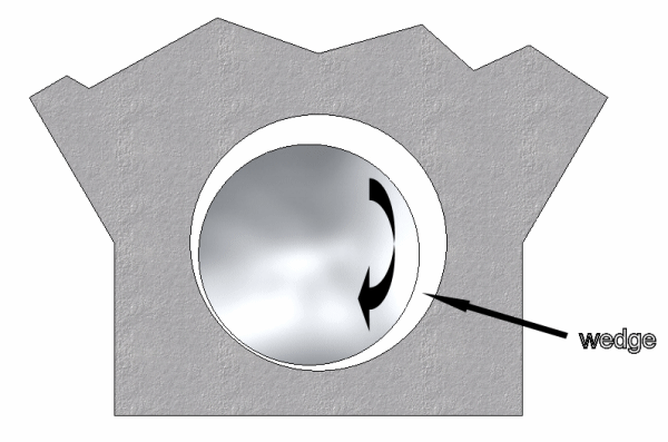
Figure 1
The lubricant, by virtue of its viscosity, clings to the surface of the rotating journal, and is drawn into the wedge, creating a very high pressure (sometimes in excess of 6,000 psi), which acts to separate the journal from the bearing to support the applied load.
The bearing eccentricity is expressed as the centerline displacement divided by the radial clearance. For example, if a bearing which has 0.0012 " radial clearance (0.0024 " diametral) is operating with a film thickness of 0.0001", then the eccentricity is (.0012 - .0001)/.0012 = 0.917.
The bearing eccentricity increases with applied load and decreases with greater journal speed and viscosity.
Note that the hydrodynamic pressure has no relationship at all to the engine oil pressure, except that if there is insufficient engine oil pressure to deliver the required copious volume of oil into the bearing, the hydrodynamic pressure mechanism will fail and the bearing(s) and journal(s) will be quickly destroyed.
It is interesting to study the pressure distribution in the hydrodynamic region of a fluid film bearing. The hydrodynamic pressure described above increases from quite low in the large clearance zone to its maximum at the point of minimum film thickness as oil (essentially incompressible) is pulled into the converging "wedge" zone of the bearing. Figure 2 shows a representative sketch of the radial pressure distribution in the load-supporting area of the bearing.
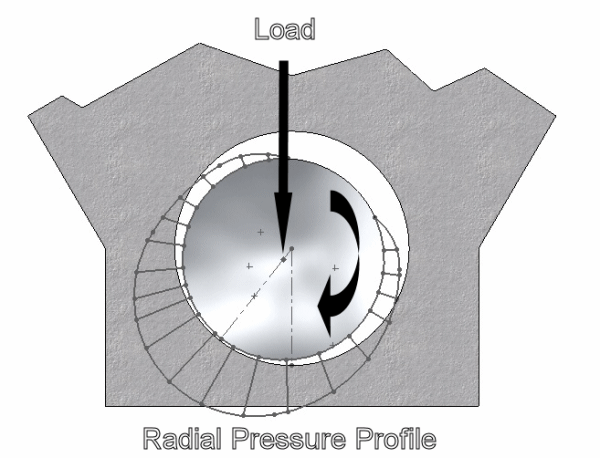
Figure 2
However, this radial profile does not exist homogeneously across the axial length of the bearing. Figure 3 shows a sketch of the axial pressure distribution profile for fully-developed hydrodynamic lubrication with a non-grooved bearing surface (insert). As the picture shows, the pressure drops off rapidly at the edge of the bearing, because oil is leaking out of the edges under the influence of the high hydrodynamic pressure. Moving inward from the edges, the pressure rises dramatically. If the bearing has sufficient width, the profile will have a nearly flat shape across the high-pressure region.
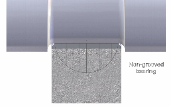
Figure 3
Long ago, it was standard practice to use fully-grooved main bearings, the thought being that the groove would provide a better supply of oil to the conrod bearings. A quick study of the axial profile of the hydrodynamic pressure distribution for a grooved surface (insert), shown in Figure 4, demonstrates how any interruption of the smooth surface of the bearing in the load-carrying region will severely degrade the capacity of the bearing.
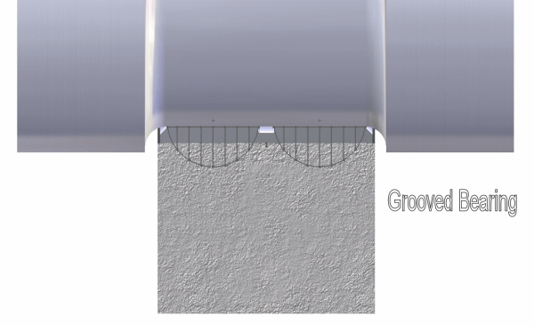
Figure 4
BOUNDARY MODE
The second mode of bearing operation is boundary lubrication. In boundary lubrication, the "peaks" of the sliding surfaces (journal and bearing) are touching each other, but there is also an extremely thin film of oil only a few molecules thick which is located in the surface "valleys". That thin film tends to reduce the friction from what it would be if the surfaces were completely dry.
MIXED MODE
The third mode, mixed, is a region of transition between boundary and full-film lubrication. The surface peaks on the journal and bearing surfaces partially penetrate the fluid film and some surface contact occurs, but hydrodynamic pressure is beginning to increase.
OPERATION
To further explain the three lubrication modes, let's examine the operation of a journal bearing from startup to steady state. Figure 5 shows a journal bearing at rest. The applied load causes the journal to contact the bearing surface (eccentricity ratio = 1.0).
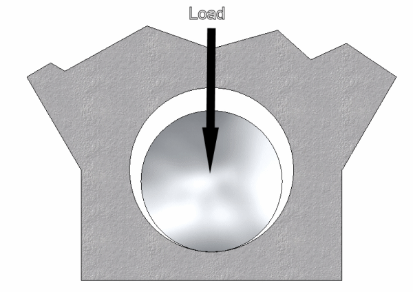
Figure 5
When motion begins, the journal tries to climb the wall of the bearing, as illustrated in Figure 6, due to the metal-to-metal friction (boundary lubrication) between the two surfaces.
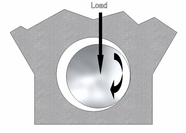
Figure 6
If there is an adequate supply of lubricant, the motion of the journal begins to drag the lubricant into the wedge area and hydrodynamic lubrication begins to occur along with the boundary lubrication (mixed lubrication).
Assuming the load and viscosity remain relatively constant during this startup period, then as RPM increases, the hydrodynamic operation strengthens until it is fully-developed and it moves the journal into its steady-state orientation (Figure 7), defined by the eccentricity (e) and the orientation angle (a). Note that the direction of the eccentricity, and hence the minimum film thickness, do not occur in line with the load vector, but are angularly isplaced from the load.
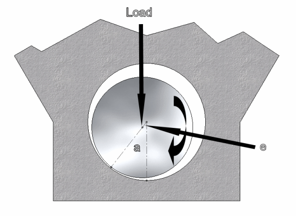
Figure 7
There are three parameters which determine the mode (boundary, mixed, hydrodynamic) in which a given bearing will operate: (1) the speed of the shaft, (2) the viscosity of the lubricant, and (3) the applied unit load.
These three parameters can be combined in the following way to form a value we can call "Bearing Operating Condition" (BOC).
BOC = Viscosity x RPM x Diameter x K / Unit Load
(Equation 1)
The Viscosity parameter is in units of absolute viscosity. The "K" value is a factor which converts RPM and Diameter into journal surface speed. The bearing unit load is the applied force divided by the projected area of the bearing (the insert width times the journal diameter).
ZN/P CURVE ("STRIBECK PLOT")
The BOC value will predict the operating mode of a bearing and the expected friction coefficient for that operating condition. The transitions between these different operating modes, and the related friction properties are illustrated more fully in the Stribeck Plot shown in below in Figure 8. This plot (also known as a "ZN/P Curve") shows the bearing coefficient of friction (on a logarithmic scale) plotted as a function Bearing Operating Condition (BOC). The values plotted on the X-axis are nondimensionalized, and are shown as a percentage of full scale.
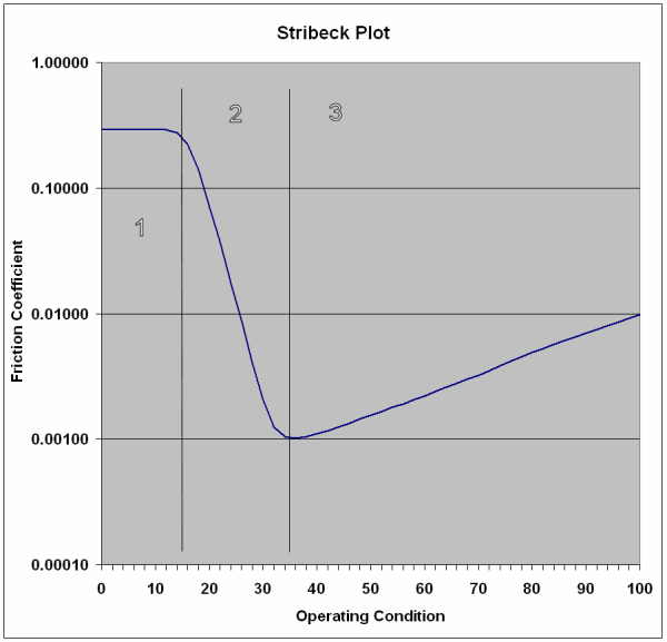
Figure 8
The two vertical lines in the plot area show the boundaries between the three operating modes. Area 1, from BOC = zero to about 15, is where boundary lubrication occurs. Area 2 (BOC = 15 to 35) is the region of mixed lubrication, in which, as BOC increases, the hydrodynamic pressure is developing and taking over from boundary lubrication. Area 3 is fully-developed hydrodynamic lubrication.
Note that the purpose of presenting this BOC (or ZN/P) curve is to demonstrate the interrelationship between friction coefficient and the BOC (ZN/P) parameters, not to instruct in bearing design.
In the definitive 2001 reference text "Applied Tribology: Bearing Design and Lubrication" by Dr. Michael Khonsari and Dr. Richard Booser (ref-2:6:12), the Stribeck Plot is shown on Page 12 and is described as a "dimensionless uN/p curve relating lubrication regime and friction coefficient to absolute viscosity". That same DIMENSIONLESS curve ("ZN/P") is shown on page 2097 of "Machinery's Handbook, 24th ed." (ref-2:22:2097)
The "BOC" entity (often known as ZN/P) does indeed have units, which depend completely on the units you choose for (a) surface speed converted to RPM and (b) unit load: psi, n/mm², mpa, etc. Various engineering texts use specific portions of the curve and use whatever ZN/P units they prefer. Others retain the dimensionless construct.
The friction coefficient values shown in Figure 8 were taken from both "Machinery's Handbook, 24th ed." and from "Design of Machine Elements", by M.F. Spotts, Professor of Mechanical Engineering, Northwest University (ref-2:2:302). Both reference works agreed that the low-point is about 0.001, the fluid film range is from 0.001 to at least 0.005, the boundary region is greater than 0.1 to as high as 0.03, and the mixed region is between the other two, as shown on the plot.
This curve illustrates that when operating in the hydrodynamic region (Area 3), if the unit load remains constant and either rpm or viscosity increase, the hydrodynamic pressure increases, the eccentricity decreases and the friction coefficient rises, increasing by a factor of 10 as eccentricity approaches zero.
However, if rpm remains fixed and either viscosity decreases or unit load increases, then the BOC will decrease. Friction coefficient decreases logarithmically down to the low point at around BOC = 35. If the unit load continues to increase and/or viscosity continues to decrease, the BOC will move into the mixed lubrication region and the lubrication mode will change from fully hydrodynamic back to the mixed mode and friction will increase dramatically. If the load increases and/or viscosity decreases even further, BOC continues to decrease, and eventually the journal asperities break through the film and the system reverts back to the very-high-friction boundary lubrication mode.
Note the values for friction coefficient. In the area of boundary lubrication, the friction coefficient is similar to that of a dry bearing (0.25-0.35). At the BOC value of 35, the friction coefficient is in the remarkably low region of 0.001, which is 50% less than the friction coefficient of deep-groove ball bearings. As the BOC increases (any combination of smaller load, higher rpm, higher viscosity) the curve shows that friction coefficient rises exponentially, approaching a value of 0.01, ten times greater than the ideal minimum. That fact illustrates why there is so much attention paid to optimizing the bearings for the application, trying to maintain the BOC in the 35-50 range.
In issues past, we have seen that combustion loads can apply forces in excess of 12,000 pounds to a rod journal. If the bearing were operating at a friction coefficient of 0.002, (BOC roughly 50), an applied load of 12,000 pounds would generate a friction load on the surface of one bearing of 24 pounds.
If the diameter of the journal carrying the 12,000 lb. is 2.50", then the friction torque lost to that bearing will be 24 lbs x 1.25" = 30 lb-in or 2.5 lb-ft. If all 5 main journals carry the same load, then the friction torque lost to the main bearings alone is 5 x 2.5 = 12.5 lb-ft, which at 9000 rpm, absorbs 21.4 HP.
If that journal diameter were reduced to 2.00", one might think that a 20% reduction in main bearing friction torque could be realized. However, for the same bearing width, reducing the journal diameter 20% reduces the projected area by 20%, which increases the unit loading, resulting in a reduced BOC for the same load, rpm and viscosity. Further, reducing the journal diameter by 20% also reduces the surface speed by 20%, which for the same RPM and viscosity, lowers BOC even further. Add in the effect of the very low viscosity lubricants some teams use, and the net effect can be a dramatic reduction of BOC. As long as the BOC stays within the hydrodynamic region, the smaller BOC will yield an even lower friction coefficient, which further reduces the bearing friction losses.
Of course in practice, it's not that big a payoff, because the 12,000 lb. load is not applied for the whole 360° of rotation. But the illustration serves to point out an area that savvy engine designers have been successfully harvesting.
SQUEEZE-FILM LUBRICATION
There is another form of fluid-film lubrication, which adds to the load capacity in applications with oscillating loads (such as a piston engine), known as squeeze-film lubrication. Squeeze-film action is based on the fact that a given amount of time is required to squeeze the lubricant out of a bearing axially, thereby adding to the hydrodynamic pressure, and therefore to the load capacity. Since there is little or no significant rotating action in the wrist-pin bores, squeeze-film hydrodynamic lubrication is the prevailing mechanism which separates wrist pins from their bores in the rods and pistons.
GEOMETRY
Crankshaft bearings are not round. The main bearing journals and crankpins that run within these (conventionally) plain bearings are perfectly round but the bearing surfaces that surround them are not. For a start, the crush that locates a plain bearing in its housing causes distortion of the housing, the nature of which will reflect the material and geometry of the part forming it. On top of this, these bearings are actually designed to be out of round.
If engine load and speed were constant and bearing geometry could always be maintained during operation a perfectly round bearing surface profile would work fine. Of course in the internal combustion engine load and speed do vary constantly and the varying loading imparted to the bearing housing constantly alters its geometry. In fact, the racing engine is an elastic device, to an extent that is not always fully appreciated. Enormous loads go both up and down the con rod, lengthening and shortening it and distorting the shape of its big and small end. In view of this contemporary steel backed plain bearings are designed to be semi-flexible rather than rigid structures.
In The Definitive V8 Engines, we showed that a naturally aspirated 2.4 litre, 750 bhp Formula One V8 running to 20,000 rpm (2006 regulations) is subject to a maximum crankpin load in the region of 13,300 lb while a naturally aspirated 5.86 litre, 850 bhp Cup V8 running to 9500 rpm is subject to about 12,500 lb. Such crankpin loads deform the crankshaft, which in turn transfers deformation to the crankcase through its main bearing journals. Thus in operation, both the rod bearing housing (conrod big end) and the main bearing housings deform.
In practice it has been established that the appropriate static profile for a crankshaft bearing is normally oval, having its minimum diameter in line with the direction of maximum load. Generally this is taken to be at 90 degrees to the parting line. Bearings are therefore typically manufactured with a wall thickness that is greatest at 90 degrees to the parting line, tapering off from that point to the parting line each side by a specified amount. This is known as bearing ovality (sometimes called "eccentricity", but that usage can be confused with the eccentricity essential to hydrodynamic lubrication) and it is tailored to the characteristics of a specific engine. For example, a heavy piston assembly and high rate of piston acceleration will result in high inertia loading at the top of the exhaust stroke that will cause pronounced stretch of the con rod, this in turn significantly squeezing the big end - a high degree of ovality is required to stop the bearing then pinching the crankpin.
BEARING STRESS
While bearings are a source of friction (including consequent shearing of the oil film) and thus heat, they are also a route for heat to escape from the reciprocating/rotating assembly to the stationary structure of the engine and, more importantly, into the circulating oil. In terms of the stress that the bearings see, it is notable that the magnitude, and sometimes even the direction of the loading varies throughout the course of each stroke. How much stress a given bearing experiences is a function of net loading and bearing projected area, which fluctuates accordingly.
Net loading varies dramatically with throttle and rpm, and throughout an engine cycle at any given throttle and rpm. For example, on the power stroke the compression / combustion loading on the con rod is compressive and this opposes the tensile inertia loading caused by piston acceleration. At low engine speed with wide open throttle there is less inertia loading balancing the piston combustion forces and, depending on the engine's torque characteristics this can impart greater net loading to the bearings than WOT operation at higher speeds. Conversely, at engine speeds above peak torque inertia forces come to dominate and the net effect on the bearings is increased loading compared to operation at peak torque rpm. However, the con rod loading that occurs in the vicinity of TDC overlap is extremely high tensile loading because there is very little cylinder pressure to oppose the piston acceleration. That load varies with the square of rpm, and can apply immense loads (and consequent deflections) to the cap-half insert.
Sustained high rpm operation is another threat to the bearings since it causes high temperature running, which in turn can cause excessive oil heating and with that a loss of viscosity. In this respect Cup oval running can be more taxing to the bearings than Formula One road racing.
An article inIssue 20 of Race Engine Technology magazine, showed an example of cavitation damage on a big end bearing from the Cosworth 2.4 litre V8 engine of 2006, which was designed to run to 20,000 rpm. As the piston approached top dead center the tendency was for the upper portion of the titanium rod's big end to arch away from the steel crankshaft journal and for the steel backed bearing to distort accordingly. There was thus a cavity formed between the bearing and the journal upon which it ran, creating a low-pressure zone in the oil film, encouraging the formation of vapour bubbles. As the piston reversed direction the combustion pressure took out the cavity, collapsing the bubbles, which added to the loading on the big end. In fact, shock waves were formed that stressed the surface of the bearing, to the extent that material could even be lost from it. Following a problem of this nature at the Malaysian Grand Prix the oil viscosity was increased. This avoided any cavitation damage until design changes could be implemented to address the problem. High shear viscosity at high temperature is critical for bearing duty as this extreme example attests. Oil development through 2006 led to a reduction in the variation of viscosity with temperature ("viscosity index").
MATERIALS AND COATINGS
Ideally a bearing material should offer low friction properties, but given that in fully-hydrodynamic operation, the bearing surface is separated from the surface of the journal by a thin film of oil, it is clearly the lubricant rather than the respective surface materials that dominates the friction generated under normal running conditions.
Therefore, if there is an adequate supply of lubrication and a suitable load / speed ratio, the material forming the bearing's working surface is not crucial in terms of frictional losses. Inevitably, however, metal-to-metal contact will occur, particularly on start up. The journal is invariably steel, and copper, for example (used as the sole material for some early bearings) running on steel has a kinetic coefficient of 0.36. However, any metal running on steel given proper lubrication has a kinetic coefficient of in the region of 0.06 (it will vary as shown in the Stribeck curve above).
In view of the unavoidable metal-to-metal contact, low friction coatings are sometimes applied to bearings. For example, one manufacturer has developed an ultra-slippery moly/graphite blend, which is suspended in an inert PTFE substrate, which provides the adhesion necessary to attach it to the top surface of the bearing. This coating, only one thou thick, which is compatible with contemporary lubricants and lubricant additives, is sacrificial - the bearing will outlive it but in the meantime it is claimed to reduce friction and wear. If there is any contact it will prevent scuffing and even absorb debris.
PLAIN BEARING CONSTRUCTION FUNDAMENTALS
Typically the tri-metal plain bearing common to contemporary high-performance engines is formed as a laminated structure having a relatively thick steel backing layer in contact with the housing, a harder, thin middle layer (copper-lead, lead-bronze, aluminum-tin, etc.) and a very thin upper layer of soft material (lead, zinc, cadmium, lead-indium, and a host of others), the top layer forming the actual bearing surface. The maximum applied pressure a bearing can carry is determined by the streength and hardness properties of the upper surface. The maximum relative velocity between the journal and the bearing is governed by the bearing's abilkity to dissipate the heat generated by the shearing of the oil film.
Except for the rare instances of built-up crankshafts, the plain bearing is split into upper and lower halves, so that it can be fitted over the journal. One half fits into the main structure, the other into the cap. Each half is known as a shell hence this type of bearing can be referred to as plain or shell-type. Normally only one of the main bearings is designed as the thrust bearing necessary to minimise axial movement of the crankshaft.
The multiple layers have been developed to provide the properties required for the specific application. While the backing will invariably be steel, a steel bearing running against a steel journal with no coating on either surface would cause high friction and wear in the boundary and mixed lubrication modes, and would provide little or no ability to allow foreign particles to embed in the material, but would instead capture them and turn them into cutting tools. Therefore, the upper layer is a softer metal, designed for minimum friction with sufficient embeddability. The idea is to allow abrasive particles to embed below the working surface and thereby minimise wear. Moreover, the softer upper layers will help the bearing act as a cushion in the face of severe operating forces. In addition to high mechanical strength and high resistance to temperature the composite bearing needs good conformability and good surface properties - it needs 'compatibility' to prevent pick up or even seizure if the oil film momentarily breaks down.
Due to the mechanical properties of the soft bearing material, one might think it would be squeezed out of the bearing due to the forces acting upon it. However, the very thin nature of the soft layer, supported by the much stronger and thicker base layer, prevents the extrusion of the soft material.
The inability of the applied load to squeeze out the soft layer is known as the principle of plastic constraint. Consider a thick layer of clay sandwiched between two plates of steel. If pressure is applied to the steel plates, the clay will deform and squeeze out the edges of the sandwich. But as the thickness of the clay gets ever smaller, it takes an ever-increasing amount of force to squeeze out more clay. Eventually, a thin layer of clay remains that cannot be extruded out without the application of an infinite amount of pressure.
A bearing needs to conform to the shape of its housing; a shape that is constantly in a state of flux since the engine is an elastic device. In view of this the bearing is designed so that when the two halves of the housing are correctly bolted together its parting line surfaces adjoin and the bearing correctly conforms to the housing, leaving the required running clearance between its working surface and the journal. However, when a bearing shell is fitted into its respective housing its edges will stand slightly proud of the housing faces so that when the cap bolts bring the parting line surfaces together there will be a slight gap between the housing faces. When further tightening brings the faces into contact the gap will have gone and the resultant 'crush' means that the bearing is compressed like a spring and applies a radial load to its housing.
Although a plain bearing is thus an interference fit in its housing locating lugs can be fitted to assist positioning during assembly. More typically each bearing shell is retained by a pin projecting into it from the housing. These lugs or pins will help avoid any danger of movement relative to the housing in operation but that is not their primary purpose and the interference fit must be good enough in this respect to ensure reliable operation.
In the case of the big end the interface between the plain bearing and its respective journal normally receives a supply of pressurised lubricant from a drilling in the journal. The relative movement of journal and bearing and the forces involved cause the oil to spread out and form the necessary film throughout the radial interface, before spilling into the crankcase.
INFLUENCES
Crankshaft main journals are subject to extremes of torsional vibration, and that influences their diameter. However, journal overlap and crankshaft balancing techniques are further factors, which may permit the use of smaller diameter and narrower journals. It is notable that the Cosworth DFV 3.0 litre V8 of 1967 had a main bearing journal diameter of 60 mm with a big end journal diameter of 49 mm. By contrast, a third of a century later a Cosworth 3.0 litre V10 typically had a main journal diameter in the range 40-45 mm, a big end journal in the range 35-40 mm.
However, there is also a very large difference between the operating speeds of those two engines. Since main journal diameter is a major factor in crankshaft torsional stiffness, perhaps the reduction in crankshaft torsional stiffness caused both by the reduced diameter and the increased length served to provide a greater separation between the crankshaft torsional resonance point and the much higher excitation frequency of today's engines.

