- The Basics of Valvetrain Technology, Part 1 -
Cams, Lifters, Pushrods, Rockers, Springs, Retainers, Valves
NOTE: All our Products, Designs, and Services are SUSTAINABLE, ORGANIC, GLUTEN-FREE, CONTAIN NO GMO's, and will not upset anyone's precious FEELINGS or delicate SENSIBILITIES
INTRODUCTION
1. This series of two articles (Part 1 and Part 2) is intended to be an introduction to the fundamentals of valvetrain technology. For a deeper dive into the vast engineering details of this subject, I strongly reccomend this magnificent book. It is authored by Dr. Billy Godbold, nuclear physicist, former chief e ngineer at Comp Cams, and currently operating his own consulting business, Godbold Engineering Solutions. Dr. Godbold is highly-sought-after by many of the giants in today's racing world.
2. This series of two articles is primarily focused on pushrod-type overhead valve (OHV) engines. The same principles apply to other types of camshaft-operated valvetrains (SOHC, DOHC, etc) with the exception of discussions involving pushrods.
3. Although many "experts" sneer at pushrod-OHV engines as being "archaic" (I heard one eurosnob refer to them as "agricultural"), the fact is that pushrod overhead valve engines are simpler and more compact when compared to other alternatives. From the crankshaft to the top of the cam cover, a pushrod OHV engine is shorter and narrower than an OCH engine of comparable layout and displacement. (For example, compare the compact, clean GM-LS engine line to the morbidly-obese Ford "modular" SOHC and DOHC engines.). GM is a huge company, with resources to match, and has a lot of clever engineers. When GM looked at new engines to replace the old SBC / BBC, they studied the available options and concluded that a compact pushrod V8 was what they needed.
4. And the fantasy that a DOHC layout is required for the best power output is convincingly put to rest when one considers the cam-in-block, pushrod, 2-valves-per-cylinder, single-4-barrel-carburetor engine used in NASCAR CUP that, until the end of the 2014 season, produced over 890 HP at 9000 RPM.
BACKGROUND
Preparing an engine to achieve maximum performance is an exercise in system engineering. It requires careful consideration in parts selection, machining, and assembly. There are dozens of components that must work in harmony to produce the most efficient cylinder filling, most efficient combustion, most efficient cylinder exhausting, and the minimization of heat losses and frictional losses, so as to deliver maximum amount of torque to the output flange of the crankshaft at all operating speeds..
As we presented in a previous section, the combined flow capability of the cylinder heads, intake passages and exhaust passages in a 4-stroke ("Four-Cycle") engine is extremely important to engine performance. However, the motion of the valves relative to the position and velocity of the piston is perhaps even more important in determining the power a given configuration can produce.
The system in which we are most interested here {a typical camshaft-in-block, overhead valve [OHV] engine} consists of a rotating camshaft located in the engine block, that generates valve motion through the valvetrain mechanism. In that mechanism, a lobe on the camshaft imparts motion to a cam follower {"lifter} of some form {flat, mushroom, roller}. The lifter moves its associated pushrod, which then moves the short end of a pivoted lever ("rocker arm") which causes the long end of the lever to push on the tip of the valve, and imparts a reciprocating motion to open the valve. In this system, closing the valve is done by the valve spring.
Figure 1 below (courtesy of Ford Motor Company ) shows typical components in this system in a cross-section view.
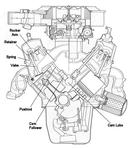
Figure 1: Pushrod Engine Cross Section (Ford Smallblock)
This system has been used in domestic automotive engines beginning in the 1925-ish time frame and became prevalent by the mid-1950's. That transition came about mainly because of the superior breathing capability provided by "valve-in-head" designs, compared to the ancient "side-valve" or "flathead" engine design, in which the valves are in the engine block alongside the cylinders.
This system saw early mass production in the Chevrolet inline-4 that was produced until 1936, and which was replaced by the Chevrolet inline 6 starting in 1935. The system began to dominate domestic production automotive engines, beginning with the 1949 Oldsmobile "Rocket" 324 cubic inch V8. Because of its inherent performance and cost effectiveness, the pushrod / rocker arm OHV system has continued to be refined, and is still used in some contemporary (2021) high-performance OEM engines.
One of the most noteworthy is the prolific family of GM 4th and 5th generation smallblock OHV V8 engines (the "LS / LT" engine family). The current crop of pushrod-OHV engines has variable valve timing (via hydraulic cam advance and retard) and selective disabling of half the cylinders in low-load operation for better fuel exonomy.
Note that there are numerous other valve-moving systems. One of the early primitive systems, known as "side valve" or "flathead" engines consists of a camshaft-in-block that operates lifters moving in bores in the block, which then directly operate the valves, which are also in the block. This type of engine is typical of a huge number of lawnmower and garden equipment engines, although a good portion of contemporary equipment engines are being re-done as pushrod-OHV engines. Figure 2 shows the layout of a typical side-valve engine.
Figure 2: Example of a Side-Valve ("Flathead") Layout
Today there is also a wide variety of different overhead cam configurations which operate the valves either directly from the cam follower ("direct-acting") or by means of any of several different rocker arm implementations. More complex systems can vary the valve timing (location of the lobe centerline) with rpm to optimize performance, and even more complex systems that have two different cam profiles for each valve, each profile being opptimized for a different engine operating range. The mechanisms reach extreme complexity where there is one cam profile to open the valve and a different complimentary cam profile which directly closes the valve, eliminating the need for a valve spring (known as "desmodromic" systems).
An excellent example of the influence which cam lobe profiles have on performance is in the evolution of what are known as "restricted" race engines. These engines are "restricted" with respect to the modifications that can be done to them, in an effort to limit the power, and therefore to limit (in theory, but not in practice) the cost of the engines.
The most common engine in this category is an iron-block 355-cubic inch Gen-1 Small-Block Chevy (SBC) V8, which is commonly limited to stock (unported, unmodified) production cast-iron cylinder heads and intake manifolds. In certain classes these engines are limited to a single two-barrel carburetor which, in stock form, can't flow more than 500 CFM of air at a pressure differential of 3" of water. This configuration represents the very incarnation of a "flow-limited" engine.
In the early development of these engines, the max power we could coax from them was in the 425 HP neighborhood (which, in itself, is impressive). Since approximately 2006, we have passed 500 HP and are continually, but slowly, approaching 525, while using essentially the same heads and manifolds (as specified by the NASCAR rules for these engines).
One major factor in that progress has been the development of ever-more aggressive cam lobe profiles, which are optimized to this particular flow-limited configuration. Of course, as you might expect, these cam profiles are very hard on the valve train components, so the successful operation of the system depends on the development of ever-more sophisticated valvetrain components. Here, we will attempt to explain why, and how different requirements can be met through the various compromises taken in cam lobe design.
Given the inherent limitations of that pushrod / OHV layout at high engine speeds, it is a huge tribute to the skills and knowledge of the NASCAR engine builders at the "Cup" level that they have succeeded in making this type of engine (358 cubic inch, roller-lifter, pushrod / rocker-arm, two-valve-per-cylinder, normally aspirated, single-carburetor V8) operate reliably at over 9,500 RPM and produce unheard-of power levels (over 880 HP as of 2016) for hours at a time. ( For more insight into these amazing engines, CLICK HERE.)
The reason we focus on this configuration is that, with respect to aircraft engines, we think this pushrod / rocker-arm system is the best solution to the compromises required to achieve a good aircraft engine: (a) maximum power per pound of engine weight, combined with (b) reasonable piston speeds and valvetrain stresses for maximum reliability. We will provide support for that argument as the article progresses.
On that subject, there is little question that an engine with a double-overhead-cam (DOHC) configuration and four valves per cylinder will produce more power per cubic inch of displacement, but that superiority occurs because of the superior breathing properties that a 4-valve configuration provides at high engine speeds and the more accurate valve motion that an overhead cam configuration provides at high engine speeds. However, reliability constraints have historically opposed the use of high engine speeds in aircraft engines, so the additional weight and size of the DOHC configuration tends to favor the pushrod / rocker arm layout.
FUNDAMENTALS
Here is a more thorough look into the details of this cam-in-block, pushrod-OHV system. In a 4-stroke engine, the crankshaft drives the camshaft at 1/2 crankshaft speed (obviously, since each valve opens and closes once for evvery two rotations of the crankshaft). The camshaft typically contains one cam lobe for each valve in the engine, although that is not necessarily the case. For example, in opposed-layout engines such as the VW-Porsche horizontally-opposed pushrod engines, Lycoming and Continental horizontally-opposed 4, 6, and 8 cylinder aircraft engines, two intake valves, each one on opposite sides of the engine, are operated by a single cam lobe driving two different diametrally-opposed followers.
As each cam lobe rotates, it contacts the cam follower (aka "lifter", aka "tappet") and drives it away from the camshaft rotational axis. The lifter (cam follower), which is constrained by the bore in which it moves, converts the rotational motion of the cam into a linear motion along the lifter bore axis. That linear motion of the lifter is transmitted to the lifter-end of the pushrod.
The other end of the pushrod moves in a somewhat less predictable manner, constrained by the pushrod socket in the rocker arm, but also disturbed by pushrod deflections, both compressive and flexural, which vary with the forces and excitations applied to the pushrod. The rocker arm rotates about its pivot point (typically either a shaft or a semi-ball on a stud), and the other end of the rocker arm contacts the tip of the valve stem and causes the valve to move along the axis of the bore ("valve guide") in which it rides. The rocker arm and its mounting components, the valve stem, and the valve spring(s) are also subject to deflection and vibration (more on that later).
At this point, it is worthwhile to become familiar with the charts that define the characteristics of a given cam lobe. These curves are very are helpful in understanding what goes on in a cam-driven mechanism.
Figure 3 shows a graph containing three profiles that define the lobe parameters for one (exhaust) cam lobe. Those profiles, as labelled in Figure 3, are the LIFT profile, the VELOCITY profile, and the ACCELERATION profile.
This type of graph is generated by taking extremely-accurate measurements of the lift profile of a lobe ( 0.00004" lift resolution every 1/10 degree of cam rotation), then differentiating (by digital methods) the lift curve to obtin the velocity curve, then differentiating the velocity curve to obtain the acceleration curve. Note: there are other, more precise cam measuring systems used by camshaft manufacturers and precision engine builders. The Adcole is a well known example of such a system.
Note that the horizontal axis is degrees of crankshaft rotation.
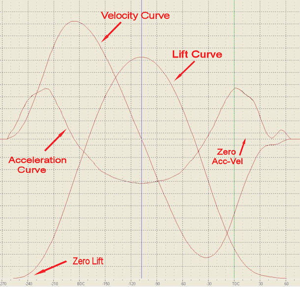
Figure 3: Cam Lobe Descriptor Curves
The LIFT curve is a plot of the distance the lifter has moved from its zero position on the base circle ("heel") of the cam (the minimum diameter section of the lobe, opposite the nose). Note that the zero-lift line in this chart is at the borttom of the plot.
The VELOCITY curve is a plot of the instantaneous velocity of the lifter as the cam moves it up and down the lifter bore. The velocity is expressed in inches-of-lift-per-degree-of-cam-rotation (or mm-per degree if you prefer). Note that on this chart, the horizontal zero-velocity and zero-acceleration line is just above the middle of the chart.
The ACCELERATION curve is a plot of the instantaneous acceleration (the rate of change of lifter velocity) that the cam lobe imparts to the lifter, as it moves up and down its bore, controlled by both the cam lobe and the valvespring. Lobe acceleration is expressed in units of inches-per-degree-per degree-of-cam-rotation, or the change in velocity per degree of lobe rotation. This is also a representation of the force (or lack of force) applied to the lifter by the cam lobe surface.
NOTE: When the term "valvespring" is used in the subsequent discussion, understand that it refers to whatever combination of valvesprings (one, two, or three,helicals, pheumatics, electronic) that exist in a given engine configuration.
It is important to understand that, as the cam rotates, the contact force between cam and lifter face (or roller) is the sum of the forces produced by
- accelerating the masses in the valvetrain (lifter, pushrod, rocker arm, valve, valvespring, retainer and locks), which varies as the square of cam angular velocity;
- the force exerted by the valvespring, which (theoretically) varies linearly with lift (helical springs only);
- cylinder pressure against the valve head, which varies with the engine configuration (boosted engines have significant pressure remaining in the cylinder when the exhaust valve tries to open, and can have significant pressure on the backside of the intake, trying to keep it open); and
- friction between moving components (pushrod and lifter, pushrod and rocker arm, rocker arm and valve tip) and between moving components and static components (lifter and bore, valve and guide).
As long as that contact force between the lifter and the lobe remains above zero, the valvetrain components are in proper contact with each other. If the contact force goes to zero, the valvetrain goes out of control. Typically that happens at max lift (over the "nose" of the cam), and lofting occurs.
Now, let's examine Figure 3 in a bit more detail. On the opening side, the acceleration value ramps up very quickly, in order to get the valve in motion as quickly as possible. As listed above, this motion is resisted by (a) the inertia of the valvetrain components being accelerated from rest, (b) the valvespring, ( c) cylinder pressure, and (d) friction.
At roughly 20% to 35% lift, the acceleration value peaks and then starts to decrease toward zero, although on the very aggressive cam lobe presented in Figure 3, the positive acceleration peaks at about 13% of lift. When the acceleration peaks, the velocity is already at or above 50% of its max value.
Whenever the acceleration value is above zero, the lifter velocity continues to increase. Note how the velocity peak occurs just as the acceleration curve crosses zero, at approximately mid-lift. When the acceleration value crosses zero into the negative range is when the foce exerted on the lifter by the cam becomes less than the force exerted on the lifter by the valvespring, through the rocker arm ratio,
As soon as the lobe acceleration goes negative, the velocity of the entire valvetrain begins to decrease to zero, which occurs at max lift ("over the nose"). When the acceleration goes negative, the valvespring takes over the acceleration function. The valvetrain components are in motion at a high speed, moving toward the valve being full open (max lift), and so the force applied by the valvespring is (theoretically) increasing linearly with valve lift.. In order to decrease the velocity of the valvetrain components to zero (at max lift), in accordance with the profile established by the lobe, the valvespring must keep the valvetrain components in proper contact with each other
Clearly, the velocity curve crosses zero at max lift. From there on, we are on the closing side of the lobe. Under the acceleration force provided by the fully-open valvespring, the velocity decreases to the negative velocity peak, where the lifter is at its max closing velocity. At max closing velocity, the lobe acceleration crosses zero and begins to exert increasing force on the lifter, and begins to decelerate the lifter toward zero velocity (valve closed).
It is interesting to note that none of these 3 curves is symmetric about the max lift point.
Notice that, as the velocity curve approaches zero on the closing side, that the lobe acceleration suddenly provides a small positive peak, which brings the velocity down to a constant value for about 15 degrees of rotation. Then the acceleration decreases to zero, allowing the valve to close gently.
That shows the nice design feature in this lobe that slows down the valve closing rate so that the valve does not slam onto the seat, and of course, bounce back open several times. That seat-bounce phenomenon is addressed later in this article.
It is sometimes believed that the cam lobe is only able to directly control the opening portion of the valve motion, by pushing the lifter away from it, and that the valvespring controls the closing half of the cycle.
As explained in the preceding discussion, that view is clearly incorrect. In actuality, the cam lobe and the valvespring, when operating correctly, work in close harmony throughout the opening-closing cycle to produce the balance of forces required to generate the desired valve motion. The cam lobe provides the positive operating force during approximately the first half of the opening cycle and the last half of the closing cycle. The valvespring provides the operating force during the negative acceleration portions of the cycle.
The actual force that a cam lobe applies to its mating lifter is, of course, relative to the RPM, or angular velocity, expressed in degrees per second, of that lobe. In order to calculate the applied force, one must know the acceleration value relative to time. As mentioned above, the lobe lobe-design values of acceleration (points on the accel curve) are expressed units of inches-per-degree-per degree. To convert those values into a time-based value for a given RPM, one multiplies the lobe-design value by the square of the angular velocity of the lobe ( [degrees-per-second]² ). That converts the lobe-design value into a time-based value, inches-per-second-per-second, from which the forces can then be calculated for different engine speeds.
All those factors can act to either increase or decrease the contact force at the cam / follower interface.
it is interesting to observe that some engine builders think that the maximum valve-open spring load ("over-the-nose" spring load) produces the greatest contact force between the lobe and the follower. In reality, that is only true at low engine speed. As rpm increases, the inertia forces produced by accelerating the valvetrain from rest on the opening side and by decelerating the valvetrain to rest on the closing side (that is, whenever the acceleration profile is above zero) add to spring force, and the sum can exceed the over-the-nose spring force applied at low speed. Further, when the acceleration curve goes below zero (the "over-the-nose" portion - see Figures 3 or 5) the valvespring is providing the negative acceleration force to bring the valvetrain to a stop, and then accelerate it toward closing. When the engine RPM is high enough that the valvespring can no longer provide enough force to overcome the valvetrain inertia, the follower separates from the cam lobe surface and valve float ("lofting") occurs. In fact, until the most recent of times, most of the NASCAR CUP engines employed intentional lofting to achieve more lift at high RPM than the cam could provide.
This phenomenon is clearly shown by the graph in Figure 4, which shows the contact stress (load) between the lifter and the lobe at low and high RPM. Note that at low RPM, the spring force over the nose is dominant, but as RPM increases, the forces on the acceleration ramps of the lobe become high, and the over-the-nose forces decrease because the spring is providing the force that keeps the lifter in contact with the lobe.
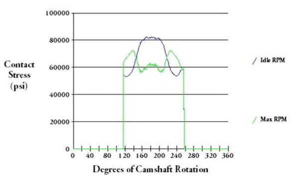
Figure 4: Cam Lobe Contact Stress vs. RPM
Further, when the acceleration curve goes below zero (the "over-the-nose" portion - see Figures 3 or 5) the valvespring is providing the negative acceleration force to bring the valvetrain to a stop, and then accelerate it toward closing.
When the engine RPM is high enough that the valvespring can no longer provide enough force to overcome the valvetrain inertia, the follower separates from the cam lobe surface and valve float ("lofting") occurs. In fact, until the most recent of times, most of the NASCAR CUP engines employed intentional lofting to achieve more lift at high RPM than the cam could provide.
Now we go back to the Figure 3 lobe profile curves, duplicated below.
Figure 5: Cam Lobe Descriptor Curves (Fig 3 Duplicated)
CAM FOLLOWER MOTION
Basic camshaft events (valve opening, closing and maximum lift) are commonly referenced to crankshaft position, because the motion of the valves needs to be studied relative to the position (and velocity) of the piston. For example, a typical intake lobe might begin to open the valve at 20 degrees Before Top Center (BTC, before the piston reaches the exact top of its stroke) and to finish closing the valve at 50 degrees after Bottom Dead Center (BDC). And yes, the piston is still moving upward when the intake valve opens and is also moving upward when the intake valve closes. This, and other apparent anomalies, are related to the dynamics of air motion, and will be discussed later.
Here (Figure 6) is a graph showing the ideal axial motion of the cam followers for one cylinder of a two-valve (one intake, one exhaust) engine as a function of camshaft rotation. The red trace is the exhaust follower travel and the blue trace is the intake follower travel. Note that the rotation axis is plotted in degrees of crankshaft rotation (which is twice the camshaft rotation, since the camshaft spins at half crankshaft speed in a 4-stroke engine). The lobes pictured here provide a maximum lobe lift of roughly 0.420 inches. That lobe lift, operating through a nominal rocker ratio of 1.6, will theoretically produce nearly 0.675 of valve lift.
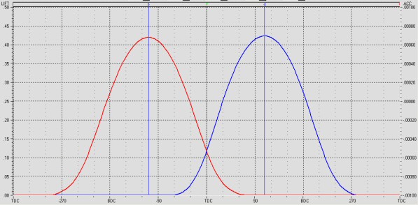
Figure 6: Cam Follower Position vs. Crankshaft Position
The commonly-quoted specifications for cam lobes are lift, duration, overlap, and lobe separation. The "Lift" spec is the maximum amount of travel the cam follower experiences as the cam lobe rotates under it. The "zero lift point" can be defined as the lift when the lobe is rotated 180 degrees from its maximum lift point, when the cam follower is said to be "on the base circle" (the constant-radius portion) of the lobe.
"Duration" is the number of crankshaft degrees of rotation during which the cam follower lift is greater than some specified value. Without knowing the lobe-lift value at which a duration is measured, the duration number is meaningless. That is because the cam lobe contains slow-motion ramps at the beginning and end of the lift period (detailed later) to take up clearances and to get the parts into motion gradually. The properties of those ramps can vary dramatically based on the intended use of the particular lobe design and the preferences of the lobe designer, so a cam specification that rates duration during those slow liftoff and landing periods is simply deceptive.
It has become an accepted industry practice (initiated by Harvey Crane back in the 1960's) to specify lobe duration as the number of degrees between the opening and closing points at which the lifter is 0.050 off the base circle.
Overlap, referring to Figure 6 above, is the number of degrees of crankshaft rotation during which both valves are off their seats at the same time, and measured as the number of degrees of crankshaft rotation during which both lifters are more than some specified distance from the zero-lift point (off base circle). Again, without this reference number, an overlap spec is essentially worthless. If we use the 0.050 tappet lift reference, the overlap of the cam shown in Figure 6 is roughly 40 degrees.
Overlap, as we will discuss later, has a very important influence on engine performance. Ed Iskenderian, one of the early developers of aftermarket camshafts, used to refer to overlap as "the 5th Cycle".
Figure 7 below is an expanded version of the lift profile of the intake lobe shown in Figure 6. The lift axis is unlabeled, but each graduation on the vertical axis represents 0.050 of lobe lift.
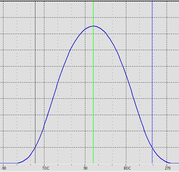
Figure 7: Cam Lobe (Lifter) Motion Profile
As is shown in Figure 7, the lobe begins to move the follower and the valvetrain at about 60 degrees before Top Dead Center (BTC) and doesn't stop moving the valvetrain until about 95 degrees AFTER Bottom Dead Center (ABC). However, it is clear that the motion (the steepness of the lift profile) closest to the opening and closing points is relatively slow by comparison to the motion at, for example, the TDC point.
Now, as you might expect, it can be difficult to determine on an actual engine, with sufficient accuracy, the exact crankshaft position when a valve begins to open or close, because of the gradualness of the motion at those points. And, the exact value of the crankshaft position relative to opening or closing points can be dramatically changed by changes in static clearance between the valve and the mechanism which moves it (rocker arm or cam follower).
That situation is not much improved if, instead of valve motion, you use lifter motion to determine these points. The reason is because a cam lobe does not start the lifter moving suddenly. Each cam lobe includes opening and closing "ramps" which allow the cam to start and to end the lifter motion in a gradual fashion. Therefore, the contemporary method of specifying cam lobe events is to state the number of degrees before and after TDC / BDC at which the lifter has moved to a distance of 0.050" from it's "zero-motion position". The zero motion position is measured when the follower is on the zero-lift portion of the lobe surface (known as the "base circle" or "heel" of the lobe) and the maximum lift portion of the cam lobe is opposite (180° away from) the lifter.
The two dark vertical lines in Figure 3 (to the left of TDC and to the right of BDC) show the 0.050 lift points on the opening and closing profile, where the steepness of the lift profile has increased quite a bit. Those 0.050 lift points occur at 20 degrees BTDC and 58 degrees ATDC.
With reference to the customary 0.050 lobe lift points, the duration of this lobe is 258 degrees (20 degrees BTDC, plus 180 degrees from TDC to BDC, plus 58 degrees ABDC). With respect to the effect on engine performance, that 0.050 duration figure is far more meaningful than what some manufacturers would advertise as the duration of that lobe (336 degrees, taken at the 0.003 lift points).
The lobe "centerline" (the point of max lobe lift, shown by the green line) is located at 105 degrees after TDC. In this example, the centerline occurs essentially midway between the opening and closing events. However, that is not necessarily the case. We now frequently use lobes with lift profiles that are asymmetric about the centerline in order to tailor opening and closing rates for various purposes.
The next curve (Figure 8) shows the same lift profile (blue) as was shown in Figure 7 above, but something has been added. The red curve represents the velocity of the follower with respect to the rotation of the cam, expressed in units of inches per degree (or mm per degree if you are metrificated)..
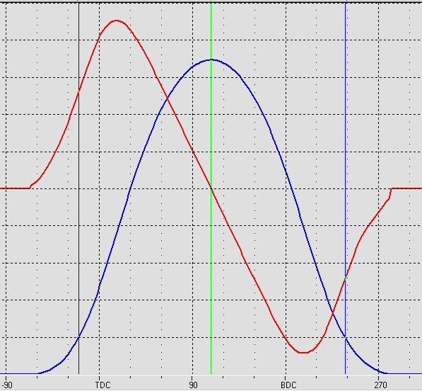
Figure 8: Cam Lobe (Lifter) Motion and Velocity Profiles
The next curve (Figure 9) shows the cam follower acceleration (black) and velocity (red) which corresponds to the cam follower lift curve (blue).
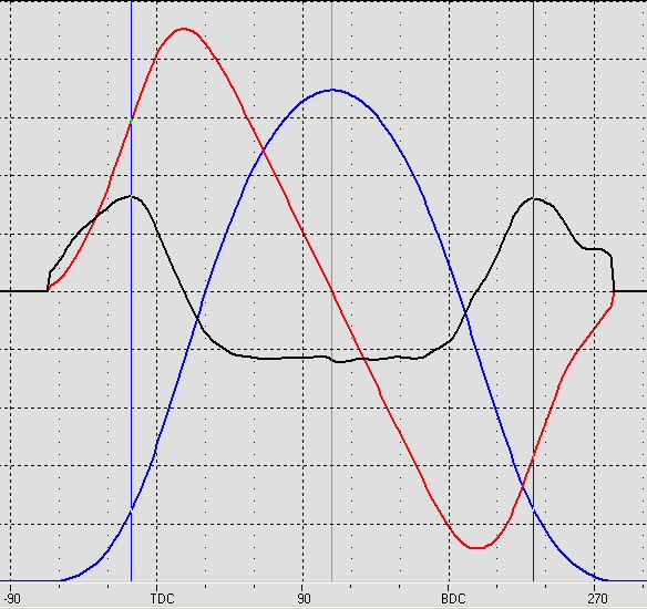
Figure 9: Cam Lobe (Lifter) Motion, Velocity and Acceleration Profiles
The cam lobe provides the "programmed" cam follower motion throughout the cycle. During approximately the first 1/4 of the cycle, the lobe also provides the force that accelerates the valvetrain components (cam follower, pushrod, rocker arm, valve, keeper, retainer and spring) in the opening direction. During the last approximately 1/4 of the cycle, the cam lobe provides the force that decerates the fast-moving valvetrain components to a stop and allows the valve to gently close on the valve seat. During the middle half of the cycle, the valvespring provides the forces necessary to decelerate the components to a stop at maximum valve lift, and to accelerate those components from that momentary stop to a high velocity back in the direction of valve closing.
The following graph shows the lifter motion caused by two different cam lobes, both of which have the same opening and closing specifications (as measured by the 0.050" travel points of the lifter). These plots are known as "lift curves". The horizontal axis is crankshaft rotation, referenced to TDC and BDC.
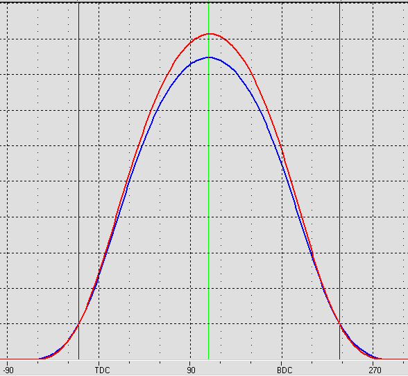
Figure 10: Cam Lobe (Lifter) Motion Profile Comparison
As you can see, both lift curves look fairly smooth. However, there is a substantial difference between the amount of force and vibration each of these two lobes impose on the remainder of the valvetrain they operate. Those differences can only be seen by comparing the curves which show the velocity and the acceleration these lobes generate (Figure 11).
Figure 11: Cam Lobe (Lifter) Motion, Velocity and Acceleration Comparisons
