- How NOT to Build an Engine -
Just a Few Examples
NOTE: All our Products, Designs and Services are SUSTAINABLE, ORGANIC, GLUTEN-FREE, CONTAIN NO GMO's, and will not upset anyone's precious FEELINGS or delicate SENSIBILITIES
Introduction
Almost everyone with an interest in engines believes he can build a world-beater ( Chevy / Ford / Toyota / Honda / whatever ) engine. The reality is very often quite different, and is proven day after day after day.
The purpose of this article is to demonstrate that building a successful automotive-based aircraft engine ( or a successful race engine ) requires a lot more than simply going to Summit, ordering a bunch of parts, and slapping them together. A successful engine is a carefully designed, carefully assembled and thoroughly tested system of well suited, well matched and well-integrated components.
Every year, the fatality rate in experimental aircraft powered by automotive-derived powerplants is many times higher than the overall general aviation fatality rate. By providing this insight into a few common mistakes, it is our hope that builders can avoid potentially deadly engine failures.
The engine presented here was built and installed in a high performance (Reno Racer) aircraft. As will be evident from the following pictures, this engine began to self-destruct the moment it was first started. It survived approximately 3 hours of flight, most of which was at a reduced power setting. During the first attempt at a high power run, it began to smoke and spew oil badly, and to lose power dramatically.
Fortunately, there was an immensely skilled pilot at the controls, who managed to get the plane back on the ground safely, in spite of being nearly blinded by the coating of engine oil on the canopy.
Subsequent teardown and analysis of the failed engine revealed that IF it had been run just a few more seconds, at least one (and probably two, Figures 25 and 26 below) of the rod bearings would have seized on the crankshaft, breaking those conrods into flailing bludgeons, which would have fairly effectively destroyed just about everything except the rocker covers and coolant pump. That is not a very desirable outcome in any event, but especially undesirable while in flight.
The pictures and discussion below demonstrate a broad spectrum of errors, including design, component selection, system integration, engine assembly and engine tuning. These errors are by no means all-inclusive. Individually, each might be thought of as a relatively common error, but it is unusual to find so many in one engine.
Engine Overview
Here are two pictures of the complete engine, prior to teardown. This engine was based on Gen-1 Small Block Chevy componentry. It had an aluminum block with a 4.125 inch bore and an aftermarket forged steel crankshaft with a 4.125 inch stroke, providing a cylinder displacement of 441 cubic inches. It had aftermarket forged steel I-beam connecting rods and aftermarket forged aluminum pistons. It was equipped with a pair of well-known aftermarket raised-port heads with large intake ports.
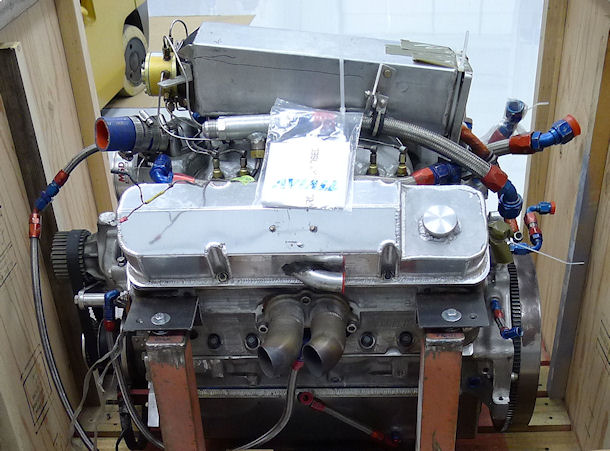
Figure 1: Complete Engine Prior to Teardown, Side View
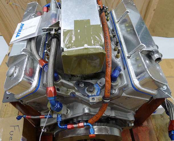
Figure 2: Complete Engine Prior to Teardown, Flywheel End View
The throttle body / fuel metering control for the engine ( missing in the above two pictures) was from an Airflow Performance Inc. (API) constant-flow mechanical fuel injection system. The fuel injection nozzles, installed in the intake manifold runners, are visible in both pictures, and the fuel flow divider is the yellow component shown on the back of the airbox in Figure 1.
This FI system is an improved version of the Bendix RSA-5 and RSA-10 fuel injection systems used on countless thousands of certified aircraft engines. The system operates on exactly the same principles as does the certified Bendix system, and, in fact, so does the mechanical fuel injection system that was delivered on thousands of Chevrolet Corvettes, beginning in 1957.
With a properly developed air delivery system, this fuel injection system is an excellent performer, and ideal for a nearly-constant speed application like an aircraft engine. However, IT DOES require a decent intake air delivery system.
Air Delivery System Errors
The air delivery system on this engine consisted of (a) the Airflow Performance fuel metering servo / throttle body (not shown in Figure 1 or Figure 2 above), attached to the forward-facing end (flywheel end) of (b) a poorly designed and poorly constructed plenum box, which in turn, bolted to (c) the central carburetor flange of an aftermarket, high-rise, single plane, 4-barrel carburetor manifold.
Figure 3 shows the entry into the airbox where the throttle body would mount. The floor ramps steeply upward from the throttle body exit, and could be expected to generate some very strange airflow patterns over the top of the downward entry into the 4-barrel manufold.
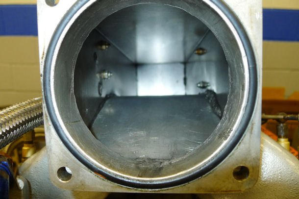
Figure 3: Entrance and Interior of Intake Plenum Box
Detonation Destruction
The next two pictures show the failure that first got the pilot's attention (copious smoke, oil covering the canopy, and dramatic loss of power). There are several more, detailed below, that would have produced a similar result after a bit more running
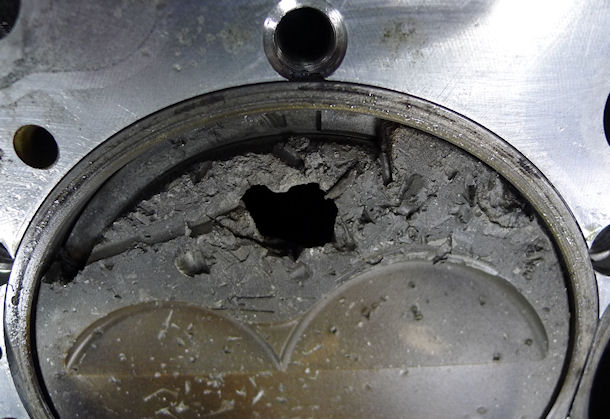
Figure 4: Cylinder 8 Pre-Ignition / Detonation Failure
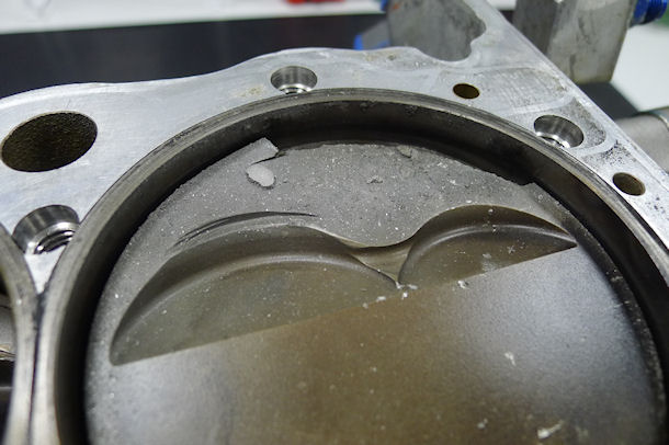
Figure 5: Cylinder 7 Detonation Failure
Shown here, pistons 7 and 8 (using GM's numbering scheme, "driver side" and "passenger side" respectively, closest to the flywheel) were destroyed by detonation and pre-ignition early in the first attempt at a sustained high power, high speed run.
Initial accusations were made against the FI system, but inspection and tests revealed that each of the 8 FI nozzles flowed essentially equal amounts of fuel for a given applied pressure.. The nature of the fuel delivery in this FI system is that all the nozzles receive the same amount of fuel pressure (controlled by the servo), and so since all the nozzles are flowing equally, then all the cylinders get equal fuel.
However, not the same can be said of the air delivery. There were indications of a major maldistribution of air, suggested by the combustion damage to cylinders 7 and 8, which apparently went very lean under the influence of a 300+ MPH wind into the inlet plenum, with the "strange-plenum-box-on-tarantula-manifold" design apparently generating massive air maldistribution, creating an oversupply of air to cylinders 7 and 8, resulting in a massively-lean condition.
By now, the observant reader will have noticed another glaring error in the build of this engine. Evident in Figures 5 and 6, the pistons did not have the intake cutouts ("eyebrows" ) in the correct location needed to clear the intake valves.
This interference began the failure of all 8 intake valves the moment the starter was first engaged. Figure 6 more clearly shows the valve interference on pistons 2 and 4, which had not (yet) suffered major detonation damage.
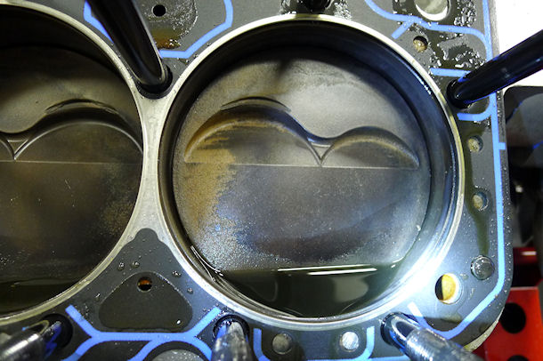
Figure 6: Piston to Intake Valve Interference
Detonation Helpers
The close-up in Figure 7 shows protruding edges of metal from the intake valve to piston interference that would have picked up combustion heat very rapidly, and would most likely have become extremely hot under full power operation, thereby contributing significantly to the detonation / pre-ignition problem.
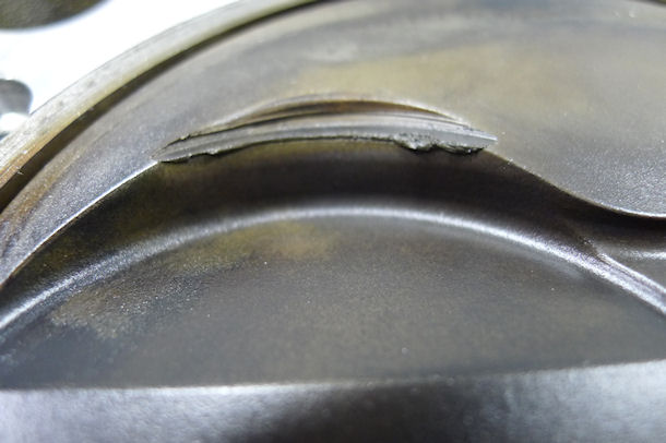
Figure 7: Piston to Intake Valve Interference Close-up
Lazy Combustion
Another problem with the piston selection is the incorrect wrist pin location ("compression height") for the stroke / conrod / block combination.
With the compressed thickness of the head gaskets (0.040) used in this build, the piston deck should have been coincident with the block deck at TDC. Figure 8 shows that the pistons, at TDC, were 0.071 below the deck, which would have expanded the squish dimension in the chamber from the ideal 0.030-0.040 to about 0.110. The net result is a very lazy combustion rate, slow flame front propagation, thus a higher probability of detonation, a higher-than-normal rate of misfires, and non-homogeneous burn patterns (as reflected by the piston crown coloration pattern).
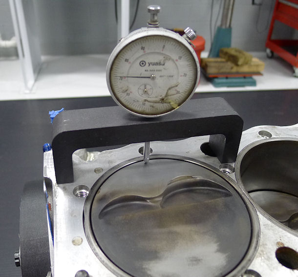
Figure 8: Compression Height Error - Cylinder 1 at TDC
Figure 9 below shows the engine with the crankshaft located at TDC Cylinder #1, as determined with a dial indicator on piston #1. The timing mark indicator (aluminum finger) shows 6 degrees of advance at an actual TDC, so IF the timing was set on this engine with a timing light, there was 6 degrees less spark advance in the engine than the mechanic was trying to set.
Talk about building a detonation machine.
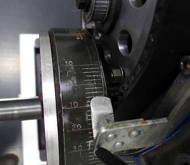
Figure 9: Timing Mark Error - Cylinder 1 at TDC
Other Top-End Errors
This picture shows a close-up of the intake ports in the head. The imprint of the manifold on the head port gasket (Figure 10) and the manifold runners (Figure 11) show the gross mismatch of the runners at the manifold-head junction, where the manifold runners were significantly larger than the head ports, causing sharp-edge-orifice effect port shrinkage and most probably a significant amount of fuel separation due to the vortices induced there.
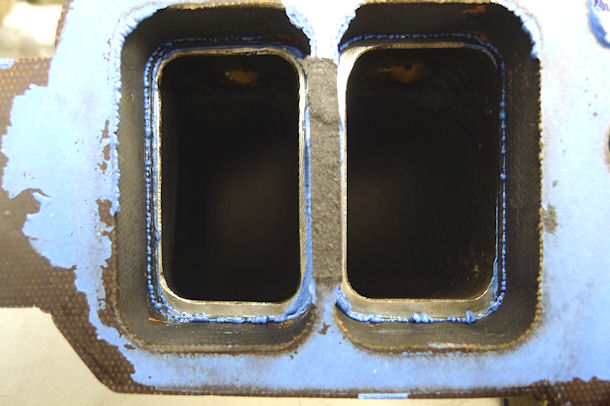
Figure 10: Manifold Runner - to - Head Port Gross Mismatch (Head Shown)
The next picture shows a close-up of the mating intake manifold, showing the level of gross mismatch described above.
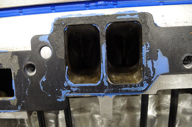
Figure 11: Manifold Runner - to - Head Port Gross Mismatch (Manifold Shown)
It is something of a tribute to the intake valves in this engine that they survived as long as they did in the wake of having endured such a severe pounding by the pistons that they forged new eyebrows in the piston tops. Clearly, the intake valves were bent somewhat so that they could not seat properly. With the seating integrity destroyed, combustion gas began leaking back across the intake valves (which are not engineered to survive the heat that exhaust valves can). The result shown below (Figure 12) was inevitable. I consider it a miracle that one or more of the intake valve heads did not pop off and grenade the engine sooner.
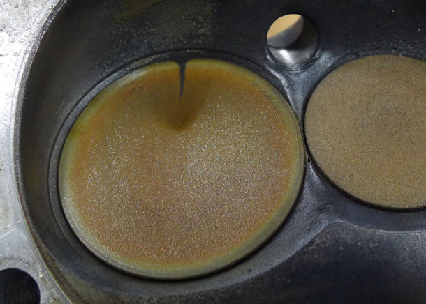
Figure 12: Intake Valve Failure
All of the exhaust valve seats were in a failed condition, typical of the one shown in Figure 13.
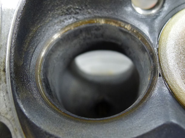
Figure 13: Failed Exhaust Valve Seats
No one knowledgeable would consider aluminum rocker arms for (a) any sort of an endurance engine, (b) certainly not for an aircraft engine, and (c) not for an engine in which it was hoped that the valve motion would in any way replicate what was intended by the selected cam profiles. Aluminum does not have an endurance limit, and the stiffness of aluminum is about 1/3 of steel. The very stiff, alloy-steel rockers used in NASCAR CUP engines are a great example of good engineering for strength and valvetrain stiffness.
The rockers in this engine were in horrible condition, as shown in Figures 14, 15 and 16. Figure 14 shows one rocker with the beginning of a failure crack (right arrow) and another with an apparent punch mark (left arrow). A careful engine builder will take extreme precautions to be sure no surface intrusions or flaws are inflicted on any high-fatugue component.
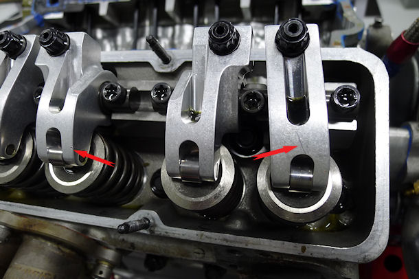
Figure 14: Aluminum Rocker Arms
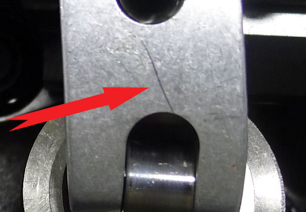
Figure15: Cracked Rocker
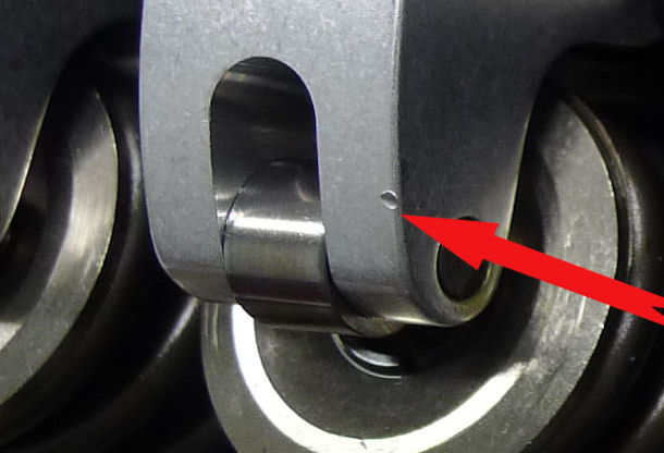
Figure 16: Damaged Rocker
Figure 17 shows one of the witness marks generated by applying Dykem to the tip and turning the engine over by hand. The purpose of that exercise is establish the correctness of the rocker geometry. Those measurements showed that the rocker geometry was not correct, and so was producing excessive rocker tip scrub across the valve stem tips. That causes excessive valve guide wear and additional valve stem fatigue.
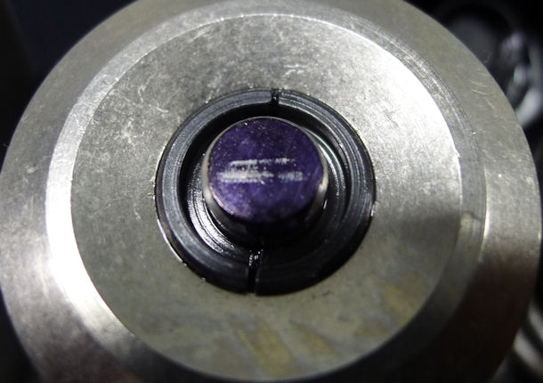
Figure 17: Rocker Geometry Witness Marks
All the intake valve locks were severely blued from overheating, and several were broken. One sample of the broken valve locks is shown in Figure 18. In addition, Figure 18 shows the sharp-corner, rectangular-shoulder valve lock configuration, which requires a matching groove in the valve stem. Those valve stem grooves have very tiny radii in the corners, which produces a large stress concentration in the valve stem, which is already subjected to severe tension fatigue loading.
Add to that the degradation of the valve alloy mechanical properties because of being subjected to far higher temperatures than what they were designed for, makes it even more remarkable that all the intake valve heads had not popped off.
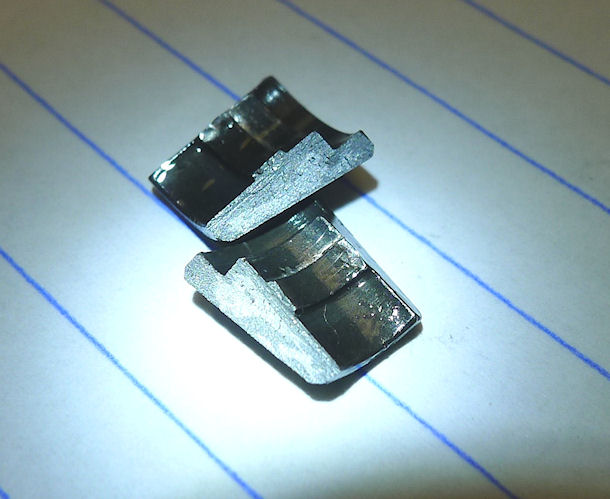
Figure 18: Blued and Broken Valve Locks
All the intake pushrods were blued and scored (Figure 19), most likely from being badly deflected by the intake valve interference and consequently rubbing heavily against nearby parts. Further, the pushrods were all of a diameter most builders would consider too small (thus lacking in column stiffness) for (a) the valve spring loads imposed and (b) the acceleration loads imposed by the performance camshaft.
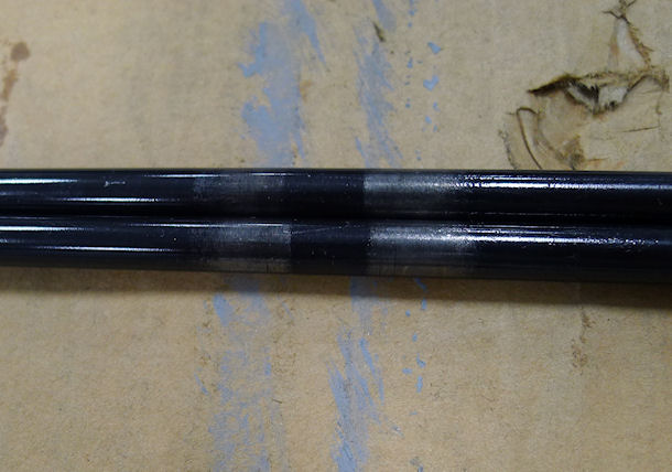
Figure 19:
All the cam followers were scored,as shown in Figure 20. That is probably from a mismatched engine oil distribution layout that was depriving the lifters, pushrods, and rockers of needed oil.
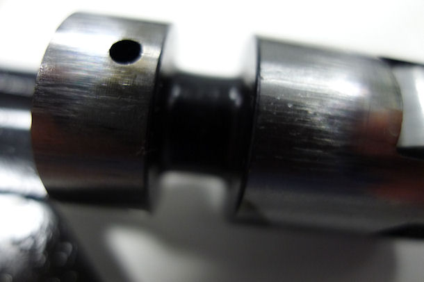
Figure 20:
Bottom-End Errors
In addition to having the wrong valve cutouts (Figure 6 above) and the wristpins in the wrong place (Figure 8 above), Figure 21 shows the under-head forging configuration of the pistons. This style of piston is an ancient design (although STILL available today) which is suitable for a road vehicle engine that will only see bursts of full throttle operation, but unsuitable for the continuous loads that would be expected in this type of application. Further, the discoloration aat the bottom of the right wristpin boss indicates wristpin binding and overheating.
A contemporary box-bridge design provides significantly better skirt strength and stiffness.
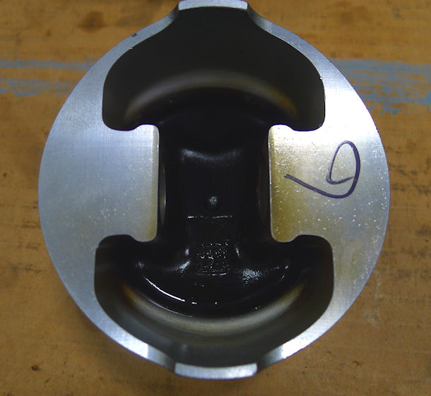
Figure 21: Ancient Piston Design
The crankshaft in this engine has a 4.125" stroke, a 2.650" main journal diameter and a 2.100" rod journal diameter. Such a configuration has only .3125 inches of crankpin overlap (see Crankshaft Design Issues). That small a value of CPO significantly reduces both the torsional stiffness and the bending stiffness of the crankshaft.
{As a point of comparison, when GM decided to produce an engine with a 3.750 inch "long stroke" crankshaft (for the SBC-400, modest-power, street vehicle engine), they increased the main bearing size from 2.450 to 2.650 in order to get a CPO of 0.500 on that engine.}
In a two-plane V8 crankshaft, the two rod journals spanning the center (#3) main are 180° apart from each other. With the SBC firing order 18436572, the center four cylinders fire sequentially (4365), and so their TDC-overlap cycles are sequential. That causes the TDC-overlap reciprocating loads applied to those two journals to add together and apply a very high bending moment across the center main. The center counterweights can offset a significant portion of that load.
I have seen crankshafts like this (long sroke, no center counterweights) completely destroy the center main bearing after only a few hours of street operation.
Figure 22 shows the crankshaft at the number-3 main, clearly showing the absence of center counterweights on this crankshaft.
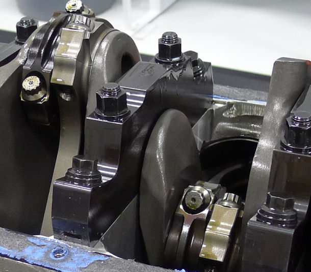
Figure 22: The 4.125 Inch Stroke Crankshaft without Center Counterweights
And as if that is not enough, reducing the torsional stiffness of the crankshaft reduces the crankshaft torsional resonant frequency. Figure 23 shows that the torsional absorber chosen for this engine is a Fluidampr ™, which is a true damper (not a tuned absorber like most other types). That product reduces crankshaft-free-end torsional oscillation and dissipates the energy as heat. The product seems to work at higher excitation frequencies, but it is not known for effectively taking out high amplitude vibrations at low frequencies.
In addition, Figure 23 shows three toothbelt sprockets mounted with a very large overhang beyond the face of the Fluidampr ™. And those sprockets are mounted on an aluminum snout with a relatively small diameter. The combined loads applied by the driven accessories (4-stage dry-sump oil pump, alternator, coolant pump, fuel pump) apply a large bending moment to the (not very robust SBC 1.25 inch diameter) snout of the crankshaft, as well as to the small diameter aluminum snout extender. That type of load (rotating beam bending) is exactly what a fatigue-testing machine uses to cause a sample to break from fatigue stress.
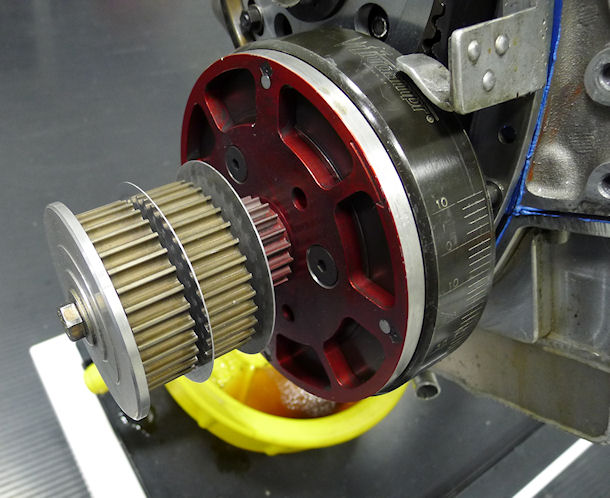
Figure 23: Badly-Overhung Accessory Drive
Figure 24 shows two major problems. The first is evidence of fretting at the main-cap-to-block interface. That is caused by minute relative motions between two mated parts that are either (a) overloaded in terms of the joint strength or (b) are poorly mated in the first place. That distress showed up on all the narrow (1 through 4) main caps.
Main cap #5 showed evidence that the assembler had applied RTV between the cap and the block, probably in the misguided hope of making a better seal of the main oil gallery. That RTV simply lubricated the joint, whose major strength and stiffness comes from friction at the mating faces.
The picture also shows another major crankshaft flaw: The conrod oil holes are flared out almost to the full width of the conrod bearing. What that does is to destroy the hydrodynamic pressure wedge that actually keeps the bearing from touching the journal. It takes quite a bit of crankshaft rotation after that interruption to re-establish the wedge.
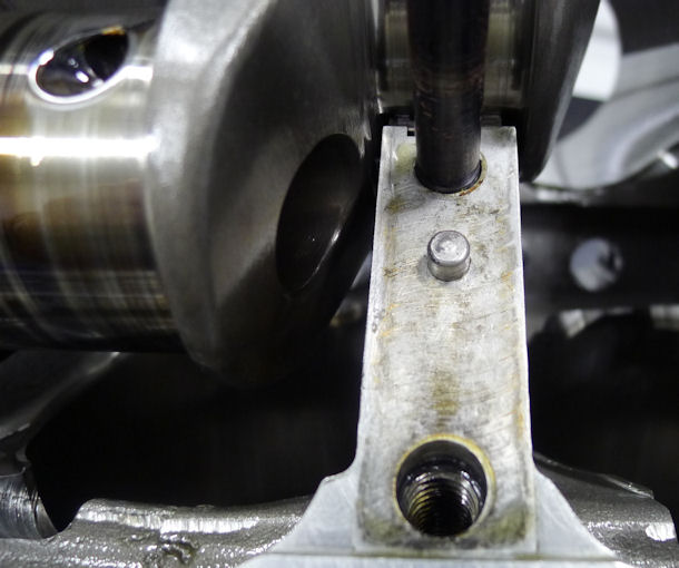
Figure 24: Main Bearing Cap Fretting
At the point of engine demise from the severe piston and valve damage shown above, there were two conrod bearings on the verge ot siezing onto the crankshaft. The first evidence is shown in Figure 25, where the rod caps of cylinders 2 and 3 can be seen to be severely discolored.
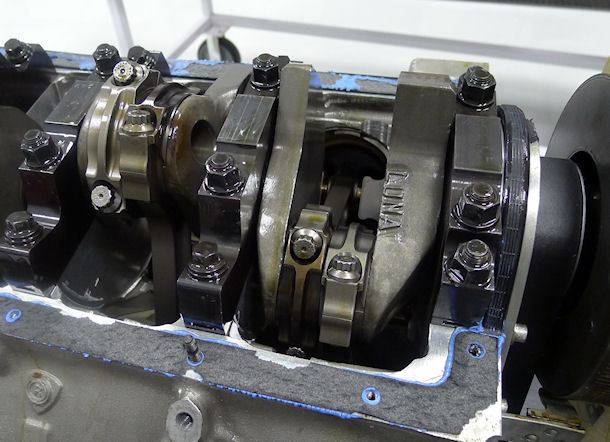
Figure 25: Incipient Conrod Failure
Figure 26 shows the cap from conrod #3. The blue color is evidence of reaching about 575°F, which is sufficient to destroy the strength imparted from the heat treatment processes during the manufacture. Conrod #2 was in similar condition.
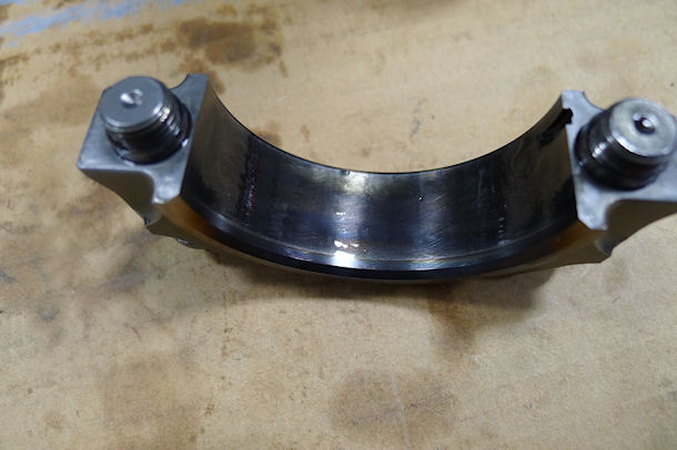
Figure 26: Destroyed Rod Cap
tFigure 27 shows one of the several destroyed rod bearings which were ready to sieze onto the crankshaft. It is interesting that these two incipient failures (rods 2 and 3) are both oiled from main journal #2. and unexpected torsional oscillations can disrupt the dynamic oil seal and consequent oil feed to rod journals.
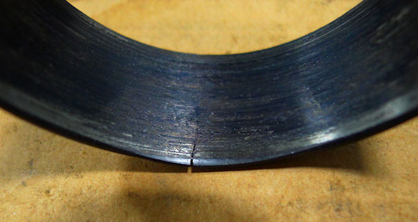
Figure 27: Destroyed Rod Bearing
Just Plain SLOPPY Stuff
Figure 28 shows an extreme example of fastener misuse. The head studs used on the engine are are ARP high-strength studs with the mating ARP high-strength nuts for the studs. ARP provides thick, hardened, high-strength washers with their stud-nut kits. Those special washers are far harder and stronger than AN-960 washers. So why there are TWO AN-960 washers stacked so as to preclude full and proper thread engagement remains a complete mystery. The condition shown here was typical across all 8 lower-row studs on both heads.
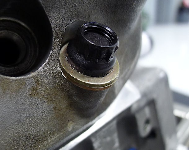
Figure 28: Sloppy Fastener Setup
Figure 29 shows a spot on the oil sump where a steel-braided oil hose was rubbing against the sump, and had nearly worn its way through. This sort of event happens when oil hoses, wires, cable clusters, or anything similar are not secured in place to pervent suce vibratory wear.
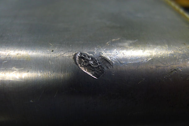
Figure 29: Aeroquip Hose Wearing Through OIl Pan
Figures 30 and 31 show that the assembler was not aware of the fact that RTV (Silicone Sealer) extending beyond the gasket boundaries is guaranteed to flake off into the oil supply under the heat and vibration of actual engine operation. By Murphy's Law, it will become imbedded somewhere that will cause severe damage: between lifters and cam lobes, into oil galleries (blocking or partially blocking them), into filter screens, and several other undesirable locations.
If an engine is properly prepared, the use of RTV on gaskets is completely unnecessary, so the presence of this much at every joint suggests either (a) there were leaking joints that had to be stopped, or (b) the assembler was completely unaware of the potential problems and the proper care to be taken when RTV is useful
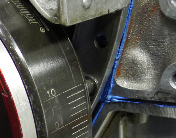
Figure 30: Excessive RTV
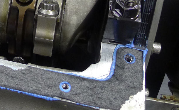
Figure 31: More Massively Excessive RTV
Conclusions
All I can say is that it is tragic that such malpractice can be present in any experimental aircraft engine. I have seen far too many examples myself. Apparently everybody and their dog thinks (and CLAIMS) that they can build a high performance engine. The analysis shown here are ample evidence to the contrary.
An extreme example of the consequences of careless or ignorant mechanical work can be seen HERE.
