- ProDrive Belt System Characteristics -
Power Transmission Properties
NOTE: All our Products, Designs, and Services are SUSTAINABLE, ORGANIC, GLUTEN-FREE, CONTAIN NO GMO's, and will not upset anyone's precious FEELINGS or delicate SENSIBILITIES
For a background on the properties of belt drives in general, see this page, then use your browser's BACK button to return here.
NOTE: In mid-2004, Gates updates their PolyChain GT engineering manual to reflect a new, lower tension ratio of 10:1 which they have found to produce suitable belt performance. All the belt loads in this section have been updated to reflect the 10:1 tension ratio.
In order to have consistency throughout this analysis, we defined (on a previous page) two operating conditions:
Max Power (123 main rotor HP) and Cruise (95 main rotor HP). There are four cases of interest presented here:
- The ProDrive belt system at Max Power, with the minimum belt preload for that power level, according to Gates recommendations;
- The same system, still preloaded for the max power condition as recommended by Gates, but operating at the Cruise condition;
- The same system, still preloaded for the max power condition, but in the stopped (not-operating) state;
- The same system, operating at the Cruise condition, with the minimum acceptable preload FOR THE CRUISE CONDITION (the most popular with ProDrive).
1. MAX POWER with RECOMMENDED PRELOAD
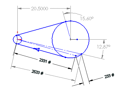
The following sketch shows the relevant characteristics of the Pro-Drive main rotor synchronous-belt drive at the Max Power condition (123 main rotor HP) with the minimum preload (10:1) for that power level.
The thin lines represent scaled force vectors, showing the driving and preload forces in the system. (The centrifugal forces with this belt are essentially negligible below 6000 ft-per-minute pitchline velocity.) The sprocket diameters are the published pitch diameters for 8-mm pitch belts of this kind, for sprockets having 34 and 144 teeth respectively. The center distance is calculated from those diameters and a belt having 224 pitches.

Toothbelt Drive at Max Power
The applied loads shown above (2331 and 233 pounds) are derived as follows. If the transmitted power is 123 HP at 2168 RPM, then the applied torque is 298 lb-ft. That torque, applied to a 34-tooth sprocket produces a driving tension of 2098 pounds (298 x 12) / (3.409 / 2). With a tension ratio of 10:1 (Gates' minimum recommended preload), the slack side tension is 233 lbs. (2098 / 9). The tight side tension (2331 lbs.) is the sum of the driving force (2098 lbs.) plus the slack side tension (233 lbs.). The resultant vector is 2533 lbs. at an angle of 12.87 degrees as shown. Note that the resultant vector (2533) is slightly less than the sum of the tight and loose tensions (2331 + 233 = 2564).
2. CRUISE POWER with RECOMMENDED PRELOAD
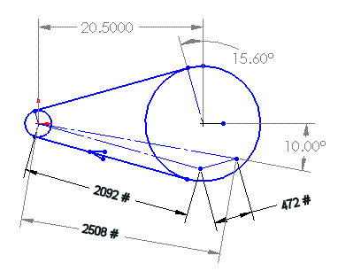
The following sketch shows the relevant characteristics of the Pro-Drive belt at the previously defined Cruise Power condition, but with the preload set to accommodate the Max Power condition (per Gates' recommendation). The slight difference in the resultant vector between this condition and the Max Power condition shown above is because, although the sum of the applied force vectors is the same, the different magnitudes slightly changes the angle (thus the magnitude) of the resultant force vector.

Toothbelt Drive at Cruise Power
The applied loads shown above (2092 and 472 pounds) are derived as follows. If the transmitted power is 95 HP at 2168 RPM, then the applied torque is 230 lb-ft. That torque, applied to a 34-tooth sprocket produces a driving tension of 1620 pounds (230 x 12) / (3.409 / 2). With the preload set for max power at a tension ratio of 10:1, the total tension in the belt (tight side plus loose side) is 2564 pounds, as shown in the max case above. The total tension (2564), minus the driving tension (1620) is twice the loose side tension (944). Therefore, the tight side is 1620 + 472 = 2092. The resultant vector is 2508 lbs. at an angle of 10.00 degrees as shown.
3. SYSTEM STOPPED with RECOMMENDED PRELOAD
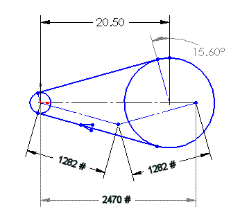
The following sketch shows the relevant characteristics of the Pro-Drive belt in the static (not operating) condition, with the preload set to accommodate the Max Power condition (per Gates' recommendation).

Toothbelt Drive (Not Operating)
The applied loads shown above (1282 and 1282 pounds) reflect the fact that, when no power is transmitted, the tension in both spans of the belt are equal, and each is half the total preload value (2564 pounds, established above in the max case). The resultant vector is 2470 lbs. at an angle of 0.00 degrees as shown. Notice how little the resultant vector changes from zero power (2470) to cruise power (2508) to max power (2533). That change is only due to the different relative magnitudes of the tight and loose span tensions.
4. CRUISE POWER with UNDER-SPEC PRELOAD
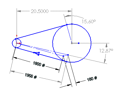
The following sketch shows the relevant characteristics of the Pro-Drive belt at the previously defined Cruise Power condition, but with the preload set to only to accommodate the Cruise Power condition at a 10:1 tension ratio. This scenario (undertensioned according to Gates' recommendations) is the only one which ProDrive will acknowledge, so it had become the default scenario for discussing the static stress analysis of the various secondary shafts.

Toothbelt Drive (Tensioned for Cruise only)
The applied loads shown above (1800 and 180 pounds) are derived as follows. If the transmitted power is 95 HP at 2168 RPM, then the applied torque is 230 lb-ft. That torque, applied to a 34-tooth sprocket produces a driving tension of 1620 pounds (230 x 12) / (3.409 / 2). To calculate the minimum preload for this cruise power case (not the max power case, as Gates recommends), using a tension ratio of 10:1 (Gates' minimum recommended preload), the slack side tension is 180 lbs. (1620 / 9). The tight side tension (1800 lbs.) is the sum of the driving force (1620 lbs.) plus the slack side tension (180 lbs.). The resultant vector is 1956 lbs. at an angle of 12.87 degrees as shown. Note that the resultant vector (1956) is slightly less than the sum of the tight and loose tensions (1800 + 180 = 1980).
This sketch is the source for the comparative analysis shown elsewhere on this site. Note how it presents the ProDrive system in its best possible light. All other scenarios show substantially higher loads imposed by the ProDrive belt system.
PRELOAD CHANGE WITH TEMPERATURE
This subject covers what we believe to be the major problem with the ProDrive belt system, that is: Because of the drastic change in preload this system experiences as temperature changes, you can never really know what preload actually exists in the system. That can be very dangerous (see Gates Issues).
ProDrive insists that temperature change does not significantly alter the loading in the system. Part of the convoluted reasoning behind that claim is based on their incorrect grasp of belt stretch (explained above).
If you think we're making this up, go check the belt tension on YOUR system when the ship has sat overnight and is at ambient temperature, and then go hover the ship for a half hour and check the tension again. You will find that the belt has tightened substantially by warming up. (Since ProDrive claims that does not happen, they must be USING different hardware than they are SELLING.)
Our measurements (taken at Homers, 2003) indicate that the ProDrive belt system components settle out at about 50 degrees F over ambient after a half-hour flight (in Ohio, in the Summer).
Our calculations (using both moduli and methodology provided by Gates Engineering) show that, for a 50°F rise, the ProDrive system gains almost 400 pounds of preload, bringing the system preload CLOSER to that required for the 90-100 main rotor cruise HP (but still undertensioned).
That increase comes from 3 sources:
- 150 lbs. from shrinkage of the belt,
- 220 pounds from growth of the 144-tooth aluminum sprocket, and
- 21 pounds from growth of the 34-tooth iron sprocket.
The total rate of tension increase is about 7.8 pounds per degree F.
It is our opinion that the only reason there haven't been more (known) belt failures is because of the substantial preload which is added to the drive once it reaches operating temperature. In fact, if the ProDrive system was adjusted to the correct 10:1 preload at ambient temperature, it would be VERY tight at operating temperature (but not in excess of Gates specs).
We speculate that one of the reasons for the high fretting and failure rate in ProDrive-equipped secondaries is the fact that, when tensioned according to ProDrive's instructions, the belt is operating in an undertensioned condition, and the self-tensioning thereby generated puts an even greater load on the shaft than we showed here.
DYNAMIC FACTORS
The effective torsional rate of the belt is the applied torque divided by the angular deflection caused by the belt stretch resulting from the difference between the preload and the tight-side driving tension.
Using the belt stretch numbers explained HERE, the belt tensile load (in excess ot the preload) on the tight side at an applied torque of 230 lb-ft (95 HP at 2168 RPM) is about 1619 pounds. That load number (1619 lbs) comes from the following calculations: 230 lb-ft x 12 inches per foot = 2760 lb-in of torque, applied to a sprocket with a pitch radius of 1.705 inches (3.409 / 2) produces a tension force of of 1619 pounds at the pitch radius (2760 / 1.705 = 1619).
Using Gates' modulus numbers, a 1619 pound load applied over a belt span of 19.75 inches causes the tight side to stretch by 0.066 inches (just over 1/16). With a sprocket pitch diameter of 3.409 inches, the pitch circle circumference is pi x 3.409 = 10.71, which, divided by 360 gives the circumferential motion per degree (0.0297 inches). Therefore, a belt stretch of 0.066 allows 2.22 degrees of deflection (0.066 / 0.0297), for a torsional rate of 103.7 lb-ft per degree (230 lb-ft / 2.22 degrees). (Thanks to Marvin Currie for pointing out to me that I had neglected a factor of 2 in the previous version of this calculation.)
Regarding alignment, the belt manufacturer recommends that there be NO MORE than 1/4 degree of angular misalignment between the driving and driven shaft in a system using this type of belt.

