- EPI Secondary Upgrade Status -
Withdrawn from Production
NOTE: All our Products, Designs, and Services are SUSTAINABLE, ORGANIC, GLUTEN-FREE, CONTAIN NO GMO's, and will not upset anyone's precious FEELINGS or delicate SENSIBILITIES
History of the Product
Our first analysis (June 15, 2003) of the RotorWay secondary shaft clearly showed that the failure mode is rotating bending fatigue. This fatigue failure occurs because the cyclic stress level applied to the shaft exceeds the fatigue strength of the shaft material. The material has lost most of its original fatigue strength because the surface finish has been destroyed by fretting corrosion, under the upper bearing in 30-mm and 35-mm systems, and in 35-mm systems, under the pressed-on anti-excursion sleeve.
As a result of all the analysis work we did on the RotorWay secondary transmission, EPI designed a new secondary transmission shaft and various parts (The EPI SuperSecondary) to fit it to the existing RotorWay autorotation clutch and tailrotor drive system.
The EPI SuperSecondary upgrade provided several high-tech features (285-ksi high-impact shaft metallurgy, greatly-increased shaft stiffness with reduced deflection, ceramic coatings, advanced heat treating procedures, increased capacity bearings, elimination of the pressfit sleeve) which were intended to make failure of the secondary shaft a thing of the past, and to allow the drive system to survive the elevated loads imposed by the ProDrive toothbelt main rotor drive system.
Our analysis shows that the fretting is caused by a combination of factors, including (a) dynamic shaft deflection from high applied loads, (b) additional deflection from engine-induced vibration, and (c) shaft design, material and hardness inadequate for high loads.
Beginning in September, 2004, we began installing our upgrade on the secondary drive systems of RotorWay helicopters. Those ships are primarily equipped with the ProDrive main rotor drive, a few have the Behuncik main rotor drive, and one has the factory chain drive.
We sincerely thank all the builders who have installed and flown our Secondary Upgrade for helping us establish the quality and reliability of our system. The first few have kindly allowed us to publish their names here: Brett Biggs, Rick Etzler, Mike Morgan, Chris Yule, Dave Fuller, John Carroll, and Mike Mazar (winner of the Kit Helicopter Grand Champion award at Oshkosh 2004).
Effective December 1, 2007, EPI has withdrawn its Secondary Upgrade product from the marketplace. There are three main reasons for that decision: (1) The relentlessly increasing cost to produce the EPI Secondary Upgrade, (2) a very high resistance of the marketplace to a price increase, (3) the unresolved nature of the Auto-Clutch slippage problem (discussed below) and (4) the huge risks involved, unjustified by the small profit margin.
We thank our existing customers for their loyal support.
The following paragraphs provide a history of the inspections and issues encountered with the system.
25 and 50-hour INSPECTIONS (July 2005)
(1) As soon as the first installation had accumulated 25 hours of operation, we disassembled it and thoroughly inspected it. This was a new ship, equipped with a ProDrive, flown by a new pilot taking instruction, so most of those 25 operating hours were at full weight (dual) and included lots of hovering.
The inspection of that system showed no signs of fretting, and the autorotation clutch surface on our shaft (which our competitor has claimed doesn't have sufficient hardness) looked completely unused (like new).
(2) Soon after that inspection, we disassembled and inspected the second installation after it had accumulated 50 hours of operation. This is also a ProDrive-equipped ship, which has about 150 hours total and is flown by an experienced pilot.
That shaft also showed no signs of fretting and the autorotation surface on the shaft also looked like new.
Both these inspections included a detailed high-magnification visual inspection of the entire shaft as well as a magnetic particle inspection ("Magnaflux").
Figures 1 and 2 show pictures of that shaft after 50 hours of operation.
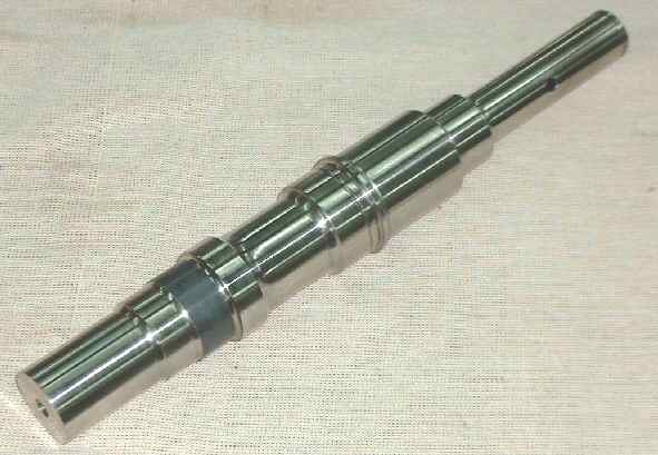
Figure 1
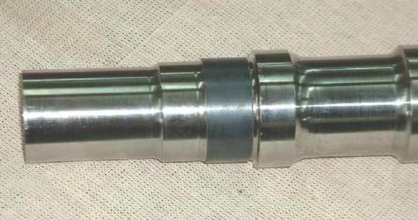
Figure 2
The pilots flying our upgrade report steady-state in-flight upper bearing temperatures as low as 35°F above ambient, and also report feeling substantially more secure about their drivetrain since installing our system. In the near future, we expect to be able to disassemble and inspect another installation after it has flown 100 hours.
RECALL (July 2005)
The owner of our first installation was not able to get his secondary re-installed for several weeks following our 25-hour inspection (described above). Soon after he re-installed the system, he phoned me to report an apparent anomaly with his autorotation clutch. I discussed it briefly with him, and asked him to remove it immediately and get it back to our shop.
The next day, (05/24/05) he brought the secondary to me. I disassembled it in his presence and quickly discovered a design error which, under certain conditions, could allow the AR clutch to fail to release during an overrun. The repair was obvious and simple, and took less than one hour.
It is very difficult to admit making a mistake, but it turns out that after machining the alternator-water pump drive pulley to accept the much larger upper clutch bearing we use with our secondary, I failed to notice that the upper clutch preload springs were not fully captured, and under certain conditions, could disengage from the upper clutch, leaving that clutch with no preload. That allowed the potential for a clutch malfunction. It also proved conclusively that the ship can operate successfully on only one of the clutch sets (see Autorotation Clutch)
I immediately phoned all the other builders who had the upgrade and explained the problem. I asked them not to fly until they had returned their secondaries to EPI for the fix. EPI recalled all the other upgrades in the field and completely disassembled them, inspected everything, corrected the error (by adding a $10 part), rebuilt them and and returned all the systems by the end of July, 2005.
During those teardowns and inspections of the 7 systems which were recalled, I found no evidence of any problem with our new shaft, upper bearings, or any other parts. There was no sign of fretting on any of the seven shafts, on which the highest time was just over 50 hours.
96-HOUR INSPECTION (March 2007)
The owner of our first installation was doing some upgrade and refurb work to his ship over the winter, so he returned his secondary system to us for inspection. According to his records, the secondary had 96 hours of operation on it, a large part of which was dual instruction and hovering.
I again disassembled his system completely and inspected it thoroughly. And again, there was no sign of any wear or distress on the secondary shaft, the auto-clutch, the bearings, or any other components.
Unfortunately, while I was cleaning the secondary shaft for reassembly, it slipped out of my hands while covered in the soapy cleaning solution. In obedience to Murphy's Law, it fell against another part in the tank and put a small nick in the ceramic coating. I was unwilling to reassemble it with that nick, so I machined the coating off and sent it, along with another batch of new shafts, to have new coating applied.
When I inspected the shafts after they returned from coating, I discovered that all the coatings showed evidence of micro-cracking on the surfaces. Extended discussions with the engineering people at the coating vendor revealed that the coating I had used previously was no longer available. But, they insisted, the one they substituted was "just as good". I insisted that obviously, it wasn't "just as good", because it HAD CRACKS.
After quite a bit of research, I found a new coating which the experts agreed should be better than the first coating for this application. So I machined off all the cracked coatings and sent the all shafts out (again) for application of this new coating. With the new coating, there is no evidence of any cracking, the surface is hard and smooth, and the bond to the metal is very strong.
I reassembled the 96-hour system and delivered it for reinstallation.
AUTO-CLUTCH ISSUES (August 2007)
(1) Dan Wilkinson's Clutch
Early in May, Dan Wilkinson, an owner of our secondary upgrade, phoned me to report he had destroyed his ship and thought that the cause was that the auto-clutch had failed to re-engage during a quick stop. The details were a bit unclear, especially with regard to which direction the ship yawed and which pedal was used to correct it.
There was some initial speculation about a variety of potential causes, including breakage of the belt. However, since a portion of the toothbelt was found melted to the large sprocket after the post-crash fire, it seems clear that belt breakage was not the cause, because if the belt broke while running, it most probably would have been thrown clear of both sprockets. Post-crash inspection of the secondary revealed that the auto-clutch appeared to work properly.
NTSB, without ever having looked at the hardware, published a statement of probable cause stating, in part:
"....The only device within the helicopter drive system that could not be determined to be in working condition was the sprag clutch which transmits engine power to the rotor drive system. The sprag clutch was not examined during the course of the investigation. The National Transportation Safety Board determines the probable cause(s) of this accident as follows: The failure of the sprag clutch which resulted in the disengagement of the drive unit....."
It is interesting that after the crash, I was told that several people had verified the correct operation of the autorotation clutch (which, BTW, is NOT a sprag clutch as claimed by the NTSB investigator; see Autorotation Clutch Properties ).
I asked Dan to send me the secondary for inspection, and told him I would not disassemble it until it could be witnessed by a knowledgeable third party. His secondary arrived here August 2, 2007, and the box was photographed and set aside until Homer Bell arrived to witness the inspection.
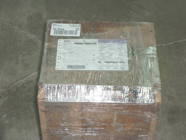
Figure 3
Homer arrived August 11th and unpacked the box personally. We verified the correct operation of the clutch assembly as soon as the system was removed from the box. Homer witnessed the disassembly of the system, and observed my inspection of the components and inspected the components himself. The following pictures were taken during the disassembly, without any special prep.
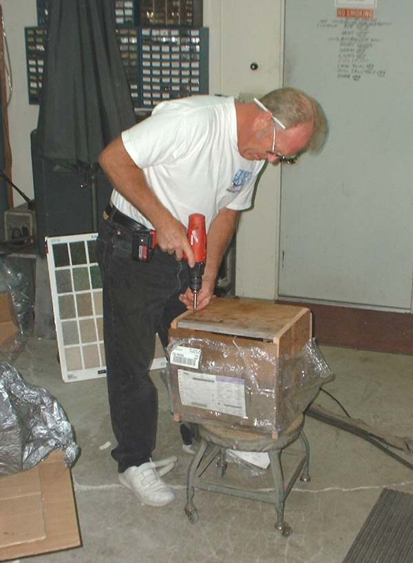
Figure 4
Figure 5 shows that the upper clutch bearing was undamaged, and the preload spring trap (EPI part; see RECALL above) was in place. The question had been asked whether this incident was related to the earlier recall; the presence of the trap shows it was not related. IF the clutch had experienced the same problem as we detected in the RECALL, it would have locked up, not slipped.
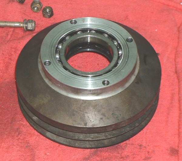
Figure 5
Figure 6 shows the presence, location, and adjustment of the upper clutch preload springs. The adjustment of the lower preload springs is hidden from view, but was verified upon complete disassembly to be set the same as the uppers. Prior to removal of the shaft and lower clutch set, the existence of apparently-sufficient spring preload was verified by manually rotating the shaft in both directions and watching the carrier move appropriately. Upon removal of the shaft, the strength of the preload was sampled by manually moving the carrier against the springs.
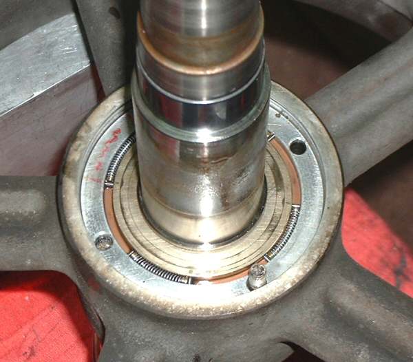
Figure 6
Figure 7shows Homer verifying the free movement of the upper clutch carrier with a small wire tool.
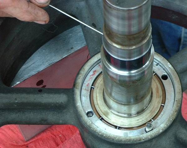
Figure 7
Figure 8 shows the secondary shaft and upper clutch carrier and rollers just after removal from the hub. The lower clutch bearing was verified to be in excellent condition. The clutch surfaces on the shaft showed no evidence of damage, indentations, deformation, wear, skidding or chattering.
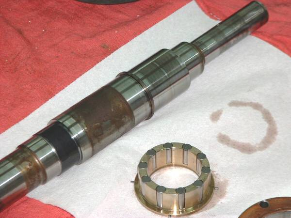
Figure 8
Figure 9 shows the 10 upper clutch rollers. These rollers, as well as the lower 10 rollers, showed no evidence of damage, indentations, deformation, wear, skidding or chattering.
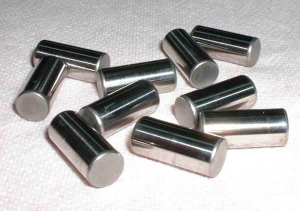
Figure 8
A possible source of clutch difficulty could be an eccentricity between the clutch surface on the shaft and either of the two (upper and lower) clutch bearing journals. In order to check for any such eccentricity, I mounted the shaft in a precision 4-jaw chuck (Figure 9) and adjusted it until there was less than 0.0001 indicated runout on the lower clutch bearing journal. The other end of the shaft was adjusted in a similar way until there was less than 0.0001 runout in the upper clutch bearing journal. Both adjustments were rechecked. Then the runout of the clutch surface was checked. In both cases, the observed runout was approximately 0.0001, coincident with the runout measurements on the bearing journals. The absence of runout in any of these surfaces is consistent with the manufacturing processes, in which all the bearing diameters and the clutch surface are finished in the same setup.
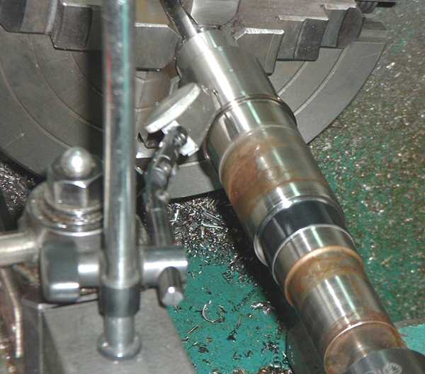
Figure 9
Regarding the matter of sizing the secondary shaft autorotation journal, we measure the factory shaft during the initial disassembly process, record that measurement on a data sheet for each upgrade (along with many other measurements) and then finish the EPI secondary to match the measured diameter of the removed factory shaft. We duplicate the factory diameter within -0.0000, +0.0001. The clutch journal on the secondary shaft from this system measured exactly the diameter which recorded in our data sheet (verified by Homer Bell).
Most of the factory shafts are marked with the journal diameter which the factory thinks the shaft has. We cross-check that marking with our measurements and with the factory size markings on the clutch cams (see Autorotation Clutch Properties). This set of clutch cams had no size markings whatever to check against. However, the roller witness marks on the cam flats were consistent with proper operation. The flats of the cams are approximately 0.520 long. The witness marks were all located approximately 0.150 from the "unloaded" end of the flats.
(2) Mike Mazar's Clutch
On July 25, Mike Mazar phoned me from Oshkosh to say that Mark Peterson had experienced what appeared to be a clutch disengagement during a quickstop which flying Mike's ship. Mike told me he had been flying the ship quite a bit during the preceding week (at Homer's meet), doing lots of autorotations, and had no previous problems with the clutch.
After Oshkosh, he removed the secondary assembly and sent it to me. It arrived here on August 8, 2007. On August 9, (with Mike's approval) I disassembled his system and inspected it in exactly the same manner as detailed above with Dan Wilkinson's hardware. (I can publish a similar set of photos of Mike's hardware, but unless someone really wants to see it, I don't see any particular value in that.)
After Homer Bell and I completed inspecting Dan Wilkinson's secondary (August 11), I showed Homer all the hardware from Mike's system. He verified that all the components appeared to be undamaged and unworn, and showed no discernable reason for a malfunction. The clutch journal on the secondary shaft from this system measured exactly the diameter which recorded in our data sheet, and is consistent with the size markings on the cam rings. The roller witness marks on the cam flats were consistent with proper operation. The flats of the cam rings are approximately 0.520 long. The witness marks were all located approximately 0.150 from the "unloaded" end of the flats.
(3) Observations
A complete examination of the clutch components of both the problem systems has revealed no obvious reason for any clutch slippage to have occurred.
I don't think it's a torque capacity issue. I would estimate that the instantaneous torque applied during the re-engagement on an auto-recovery can be quite a bit more than what goes on during a quickstop. The clutch has already been shown to be capable of operating with one clutch set disabled. There have been no reported problems during autos and recoveries, but the clutch dynamics during a quickstop are somewhat different from an auto.
In entering a quickstop, typically one pulls back the cyclic and lowers the collective an appropriate amount to keep from gaining altitude, and rolls off the throttle an appropriate amount at the same time to maintain rotor RPM constant. (RotorWay pilots have told me that in a RotorWay, you don't need to pull back on the cyclic to initiate a quickstop; the simple act of lowering the collective causes the ship to pitch up. However, the resulting airflow dynamics are the same.)
The airflow through the main rotor during the pitch-up maneuver unloads the auto-clutch to some degree or another, and depending on the aggressiveness of the maneuver, could unload the clutch completely.
In the entry to a quickstop, the cam rings and the secondary shaft are both rotating at about the same speed. In that circumstance, any torque transmitted from the cam rings to the secondary is trying to lock the clutch, but if the main rotor aerodynamics unload the clutch and try to drive the secondary even 1 RPM faster than the cam rings, then the friction between the shaft and the rollers will disengage the clutch. At the same time, centrifugal force is trying to disengage the clutch (see Autorotation Clutch). If the centrifugal action overpowers the springs, it could allow the clutch to disengage enough to let the engine run away, especially if the pilot has not rolled off the throttle during the maneuver, or if the correlator is poorly adjusted (as Homer says many are).
If the engine overspeeds, then the clutch is hopelessly disengaged until the engine speed is reduced so as to bring the clutch hub speed well below that of the secondary shaft, allowing the springs to push the rollers back into near-contact with the shaft, helping to re-engage the clutch.
That seems quite different from the scenario during an autorotation, where you deliberately split the needles by lowering collective and rolling off the throttle. In that case, the secondary maintains normal speed, but the cam rings are turning several hundred RPM slower than the secondary shaft (the secondary turns 4.2 times faster than the main rotor). The springs are pushing the rollers toward engagement, and friction between the rollers and the shaft is dragging the rollers away from engagement.
BTW, Mark Peterson said the way he recovered was to roll off the throttle completely, then bring it back up gently (great emergency-response, considering the proximity to the ground and the surprise factor).
So the remaining unknown is the question of just how much spring preload is required to overpower the clutch's designed-in tendency to disengage as RPM increases (see Autorotation Clutch Properties). We duplicate the factory preload spring settings to the extent it is reasonable. However, in some of the factory secondaries we have disassembled, there is quite a bit of variation in the settings. In some, it was quite evident that the spring load was excessive, both from the existing gap the factory had set and from the fact that the surface of the secondary shaft (where the rollers drag during an auto) had been overheated due to friction (the blue color was a dead giveaway).
I know this sounds like I'm blaming the clutch, but I'm really just trying to discover what can be done to solve the problem. Is it only with my secondary upgrade, or will a stock RW do the same thing in a similar situation?
There was a recent claim made by a renowned salesman to the effect that we don't get sufficient hardness on the secondary shaft clutch journal. I have repeatedly presented data showing that the hardness of that journal on the EPI shaft is at least 60 HRc (one point above many factory shafts). The fact that there is no measurable wear or deformation on either of these two shafts (nor on any of the other shafts we have inspected after as much as nearly 100 hours of service) strongly suggests that the hardness is as I claimed.
That same expert also claimed that we did something to cause the two carriers to contact each other in the center of the clutch, causing them to somehow jam.
That claim suggests strongly that the salesman is rather unfamiliar with the RotorWay autorotation clutch mechanism. First of all, the width of the cam ring is approximately 0.045 greater than the width of the portion of the carrier which fits inside the cam ring. That gives approximately 0.090 separation between the carriers when they are assembled in the pulley hub, governed completely by the width of the hard cam rings. Secondly, there is an 0.032" thick spacer which goes between the ends of the two carriers to prevent such an interference from happening. The 0.032" spacer floats in this 0.090" space.
This relationship is shown in the following two cross-sectional photos, in which I have highlighted the upper cam ring in green, for clarity.
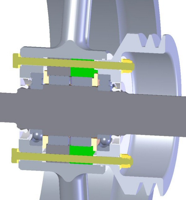
Figure 10
In Figure 11, the upper cam ring is highlighted in green and the rollers have been removed to clearly show the relationship between the carriers. You can click on the picture below to see a larger version.
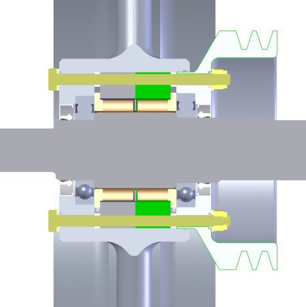
Figure 11
AUTO-CLUTCH UPDATE (August 22, 2007)
Today I got an email from a web-friend (Graeme Smith) who told me a sad tale about his RotorWay auto-clutch which slipped under power. He told me that he had disassembled and inspected his, and he suggested a couple of possibilities which I had not thought of.
The most revealing one was the fact that he had done measurements which showed that when the secondary shaft was turning with essentially zero runout (such as it does with respect to the ID of the clutch pulley hub when mounted in the upper and lower clutch bearings) that if you lock up a clutch set on the shaft and measure the OD of the cam ring, that there is a significant amount of runout.
What that means is that since the cam rings are being held firmly concentric with the ID of the pulley hub, thus concentric with the clutch journal on the secondary shaft, that the pitch diameter of the rollers is not concentric with the secondary journal, and only a few rollers will engage.
I thought this observation was interesting, but perhaps a bit exaggerated. So I took Dan Wilkinson's secondary, installed the upper clutch set on the shaft, and again set it up in my lathe and adjusted it for essentially zero runout (0.0002). I then locked the clutch and put an indicator on the OD of the clutch ring and turned it to find the peak. At that point I set the indicator to zero and marked the OD of the clutch ring with angular positions (0, 90, 180, 270). That setup is shown in the following picture. (You can click on either picture to see a larger version.)
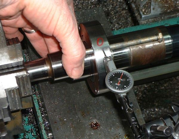
Figure 12
Next, I turned the entire assembly, keeping the clutch locked in the same position, with the indicator still in place. I was amazed to find that there is 0.004 (FOUR thousandths) runout in the OD of the cam ring.
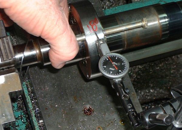
Figure 13
I tried the same experiment with the cam ring positioned in different spots relative to the secondary shaft. The lowest runout I recorded was 0.0015 (one and a half thousandths), and the worst was the 0.004 value.
It is interesting that the runout varies relative to the location at which the clutch engages. That might explain why the slipping does not occur constantly. But when it is in the 0.004 eccentric location, it seems impossible to me that more than just a few rollers will engage, severely limiting the capacity of the clutch. Add to that the centrifugally-disengaging property and it becomes more worrisome.
UPPER BEARING ISSUE (August 2007)
Early in August, I got a call from an owner who had bought a ship from Homer. That ship had the EPI secondary in it. The owner had flown it approximately 50 hours, part of that time with Orv Neisingh. The owner told me he had detected signs that the secondary shaft was loose in the upper bearing. After hearing the symptoms, it sounded to me as if he was correct. He removed the secondary and sent it to me. It arrived here August 10th (in very battered condition as the result of an incredibly poor packaging job).
I disassembled it immediately and verified that indeed, the coated surface of the secondary shaft was about 0.020 diameter smaller than it had been during assembly. There was clear evidence that the inner race had spun on the shaft. The bearing inner race had lost about 0.0005 of material off the ID. The shaft coating was intact; the 40mm bearing looked completely undamaged; there was no discoloration to either the shaft or the bearing. Because of the bearing retention method used on our shaft, there was no danger of the secondary shaft moving vertically with respect to the bearing.
This shaft was one of the first put into service with the new coating ( described in 96 HOUR INSPECTION above). At present, I don't know why the shaft got loose in the bearing. As of March, 2008, no other problems with this coating have been reported.
Figures 14 and 15 show the shaft after the upper bearing was removed.
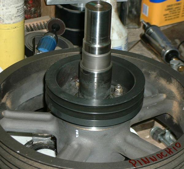
Figure 14
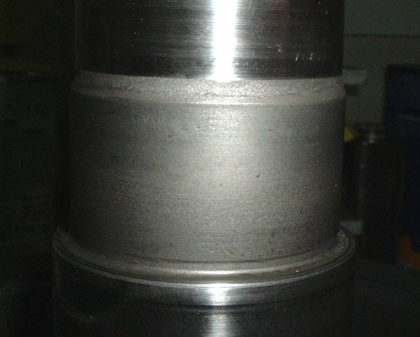
Figure 15
Figure 15 shows a close-up of the coated portion of the shaft. Although a considerable amount of the coating wore away (0.010 off the surface) there was no apparent damage to the shaft, and no overheating to either the shaft or the bearing. In fact, while the ship was being flown in this slipping condition, upper bearing temperature was being reported to be in the normally-expected range. Those observations are encouraging with respect to the toughness of the new coating.
