Autorotation Clutch Properties
Properties and Operation of the RotorWay Autorotation Clutch
NOTE: All our Products, Designs, and Services are SUSTAINABLE, ORGANIC, GLUTEN-FREE, CONTAIN NO GMO's, and will not upset anyone's precious FEELINGS or delicate SENSIBILITIES
This page presents a description of the properties and operation of the RotorWay autorotation clutch. The following picture shows an exploded view of that clutch.
The autorotation clutch in most certified helicopters is a "sprag" clutch, with centrifugal-engagement dynamic properties. A sprag clutch operates by wedging a set of dogbone-shaped cam elements ("sprags") between two cylindrical surfaces.
By contrast, the RotorWay clutch is a roller-type of clutch, which has centrifugal-DISengagement dynamic properties. A roller clutch operates by wedging a set of cylindrical rollers between a flat ramp surface and a cylindrical surface. Typically, roller clutches have a lower capacity than a similar-sized sprag clutch.
The remainder of this page will describe the functional elements of the RotorWay clutch and explain how they operate.
Figure 1 shows an exploded view of the autorotation clutch. As the picture shows, the autorotation clutch fits inside the center of the 8-sheave V-belt pulley. The pulley rides on the secondary shaft by means of two ball bearings, an upper and a lower. The pulley is driven by the engine in a clockwise direction (looking down) and transmits motion to the secondary shaft by means of the autorotation (one-way) clutch.
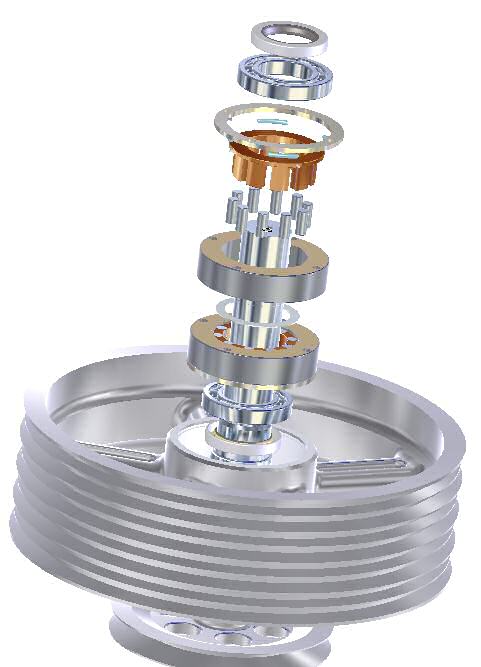
Figure 1
The autorotation clutch consists of two mirror-image roller-clutch sets, the upper set and thelower set. Each set consists of the following components:
- Ten cylindrical rollers which are carried in
- a brass retainer and which are wedged between a hardened surface on the
- secondary shaft and ten flat surfaces on the
- outer "cam ring". The brass retainer is loaded toward engagement by
- four springs.
The operation will be more clear after viewing the next few pictures.
Figure 2 shows the roller carrier. Note that on its outside rim, there are four small pins. The loading springs act against these pins to load the rollers toward the engaged position.
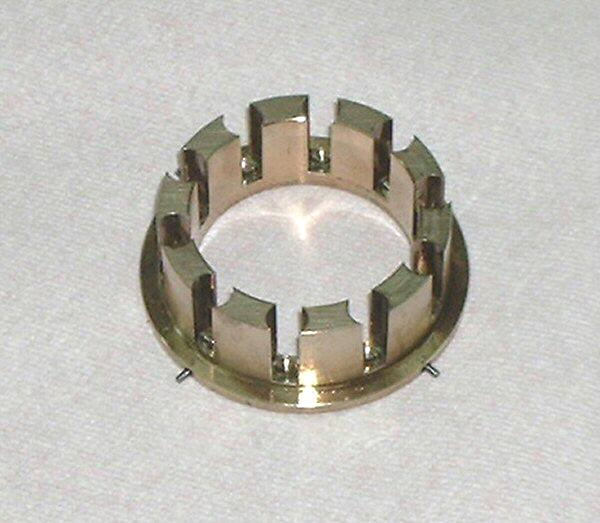
Figure 2
Figure 3 shows the carrier with a full complement of rollers.
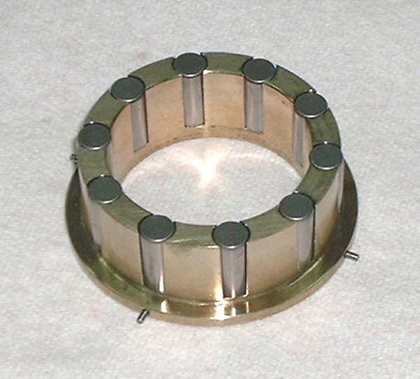
Figure 3
Figure 4 shows a cam ring. The cam ring is a round steel ring which has 10 flat, hardened surfaces machined on its inner face.
Note the markings on the cam ring. A few of them have a date written on them (like this one: 4-1-88). Most of them have size variations scribed on them. The "+07" on this ring means that the diametral distance across the flats turned out such that the mating journal surface on the secondary shaft should be no less than 7-ten-thousandths (0.0007) larger than the nominal size of 1.7500. If the journal is smaller than that target size, there is a large risk that the rollers can jam over-center during an impact engagement. Most RotorWay secondary shafts are within one ten-thousandth of this target value. However, occasionally they aren't so close. We have seen one which was 40 ten-thousandths smaller than the target size.
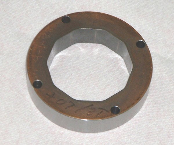
Figure 4
Figure 5 shows the cam ring with the rollers and carrier installed. The hardened journal surface of the secondary shaft goes in the center of this assembly. The orientation shown here is that of the lower clutch set, with the spring pins on the bottom.
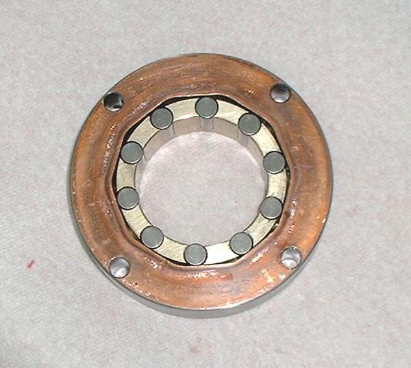
Figure 5
Figure 6 shows the same assembly turned over as it would be for the upper clutch set. In this view it is easier to show the operation of the loading springs.
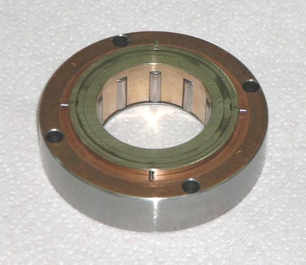
Figure 6
Figure 7 shows the fully assembled upper clutch set as it would be installed into the pulley hub. Note the thin aluminum ring on top of the cam ring. That ring provides the outer wall of the spring cavity as well as the fixed stops for the loading springs. The four small pins radiating inward from the ID of the ring are the fixed stops for the loading springs.
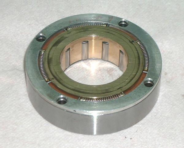
Figure 7
Figure 8 shows the lower set installed in the pulley hub. In this view, it is easier to visualize the operation of the clutch.
The pulley is being driven in a clockwise direction by the engine. The cam rings are attached to the pulley both by the four through-bolts and by the clamping forces generated when these bolts are tightened to the appropriate torque. The roller carriers are spring-loaded in the counterclockwise direction, toward the engaged position. Whenever the cam rings are trying to turn clockwise and the secondary shaft is resisting that motion, the flats on the cam ring wedge the rollers into high-stress contact with the journal on the secondary shaft. The resulting friction between the rollers and the shaft have the effect of locking the shaft and the pulley together.
If the pilot rolls off the throttle so that the pulley is no longer turning as fast as the secondary, you can see that the shaft will turn faster than the cam rings, and the resulting friction drags the rollers out of wedged engagement, allowing the shaft to spin freely clockwise, faster than the pulley.
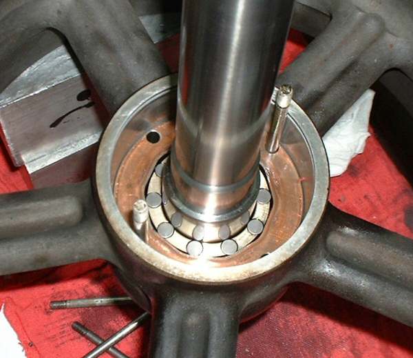
Figure 8
During this slipping action, when the speed of the secondary shaft exceeds the speed of the clutch cam rings, the springs are continually trying to force the rollers back into engagement with the shaft. However, centrifugal force is pushing the rollers against the cam flats. By being forced against the cam flats, the rollers are being driven toward a larger radius (trying to climb the flats toward the radius-junction with the adjacent flat) and are therefore being driven away from contact with the secondary shaft.
This centrifugal action causes the RotorWay clutch to have a property known as centrifugal disengagement. That is to say, as the RPM of the clutch cam and rollers increases (ie, engine RPM and thus the RPM of the 8-sheave pulley), the centrifugal force produced by the clutch elements (rollers, sprags) tends to move the clutch elements toward disengagement. Once a centrifugally-disengaging clutch has disengaged due to centrifugal forces, its RPM must be reduced before it can re-engage.
In each clutch set, there are four small springs which oppose the centrifugal disengaging force. The rollers don't have to move much; a few thousandths of motion is all the difference between fully engaged and fully disengaged.
Spring preload adjustment is accomplished by the relative positioning of four pairs of retaining pins. In each pair there is a fixed pin and a moving pin. The fixed pins are set at 90 degree spacing into the ID of the aluminum ring (the "fixed retainer", shown in Figure 7). The moving pins are set at 90 degree spacing into the OD of the roller carrier, shown in Figure 6. Adjustment of the spring preload is done by assembling these components with their relative positions set so as to provide approximately the desired preload. The approximation is a result of the design.
There are only a few combinations of positioning which provide distances between the pins which are meaningful for the springs. For each of the two roller clutch sets in the RW system, there are 10 different relative angular positions of the roller carrier within the clutch cam ring. Each relative position is separated by 36 degrees (360 / 10). Of those 10 positions, 5 are redundant (5 x 36 = 180), so there are 5 unique positions. For each unique angular position, there are two possible orientations of the fixed retainer, giving a total of 10 different spring gap values. Of those 10 possible values, only two are reasonably applicable to the RW springs. The other 8 combinations produce no preload (no spring compression at all), far too little preload, or spaces so small the springs won't fit. Most of the factory clutches we have examined are set to the same spring preload position.
Roller clutches and sprag clutches can be designed to be either the centrifugally-engaging type or the centrifugally-disengaging type. If one considers the o peration of a helicopter autorotation clutch, it would appear that a clutch with the centrifugal engagement property (ie, the clutch is energized by centrifugal force toward tighter engagement) would be much more desirable than the opposite.
The Specialty One-Way Clutch Division of Borg-Warner Transmission Systems produces autorotation (sprag) clutches for many of the world's certified helicopters. I had a discussion with the Engineering Manager of the group in that division which provides the autorotation clutches for MANY of the existing commercial and military helicopters in the world. During that discussion, I asked him if there was any reason he could think of that one would use a centrifugally-disengaging clutch in the autorotation system of a helicopter. After a long silence, he said "Of course not". He also told me that all the sprag clutches they supply for helicopter autorotation clutch applications are of the centrifugally-engaging type.
