- ECR Engines' Dyno Adapter System -
A Huge Reliability Gain for the ECR Active AVL Dyno Cell
NOTE: All our Products, Designs, and Services are SUSTAINABLE, ORGANIC, GLUTEN-FREE, CONTAIN NO GMO's, and will not upset anyone's precious FEELINGS or delicate SENSIBILITIES
The testing of the performance characteristics of race engines has become increasingly more complex and sophisticated in recent years, especially at the top levels of motorsport.
The system commonly used for testing the output of piston engines across a defined operating range are known ad dynamometers. There are engine dynamometers to test engines that are not in vehicles, and chassis dynamometers to test engine output at the driving wheels. Dynamometers can generally be grouped into two categories: Active and passive.
A "passive" dyno is one which basically consists of (a) a power absorber (water brake, hydraulic brake, eddy current brake, etc.) and (b) some rudimentary form of control system which varies the resistance of the absorber so as to just match the torque being produced by the engine (for a steady-rpm run) or which varies the absorber load so as to allow a preprogrammed engine acceleration rate (100 rpm/sec, 200 rpm/sec, etc) over the span of a preprogrammed rpm range (known colloquially as a "pull").
The imposition of stringent emissions requirements on motor vehicle engines created a need for more sophisticated engine testing, and caused the OEM's to develop highly sophisticated real-time combustion analysis systems and sophisticated "active" dynamometers.
An "active" dyno is a system in which the absorber is typically a motor-generator with a permanent-magnet-rotor, and is controlled by a very sophisticated computer-based system which allows test engineers to define and execute complex combinations of test parameters. This type of dyno provides far greater capability for comprehensive and exhaustive engine testing than does a passive system.
An active dyno can (a) be driven by the engine and measure engine torque and RPM, (b) drive the engine and measure the driving torque and RPM, and (c) do combinations of those operations. By using preprogrammed schedules, the dyno can simulate full or part-throttle accelerations, upshifts, long runs at full power, closed-throttle decelerations, downshifts, and various combination. Race engine developers use those capabilities to accurately simulate lap after lap around a given race course, thereby testing the actual usage which a race engine experiences throughout practice, qualifying and running an entire race.
In the not-too-distant past, the engine testing program for many racers consisted of a few "pulls" on a passive engine dynamometer ("dyno"). Contemporary top level teams in motorsport (NASCAR, IndyCar, F1, Moto-GP, etc) use complex, environmentally-controlled engine test cells equipped with active dynamometers. An example of such a facility is the active test cell at ECRE (Earnhardt-Childress Racing Engines) pictured below.
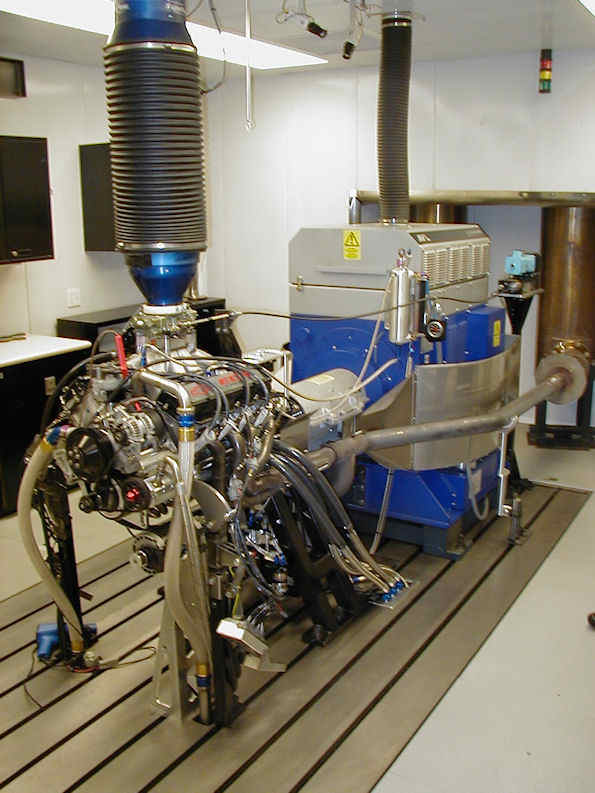
Active AVL Dyno at ECR Engines
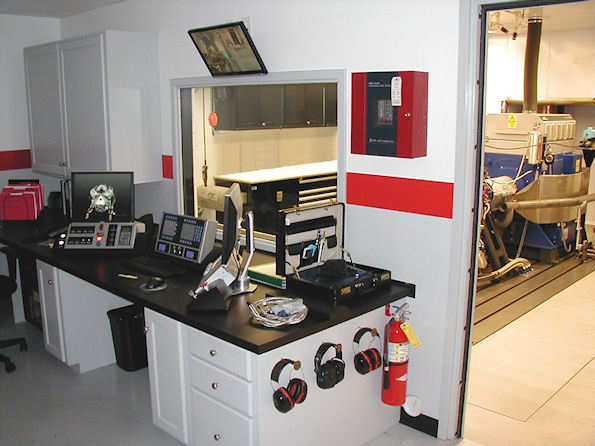
Active Test Cell Control Room at ECR Engines
ECR Engines is a high-performance engine production, research and development company at the Richard Childress Racing campus in Welcome, N.C. ECR Engine’s core business is to support NASCAR Cup and Xfinity Partners with engine leases. However they have expertise in other professional motorsports powertrain support including sportscars (IMSA and TransAM) and dirt track engines. Additionally, ECR Engines have the capability to support military and alternative energy projects.
ECR Engines have earned more than 200 victories, including the Daytona 500, the Brickyard 400, 24 Hours of Daytona, 12 Hours of Sebring and have helped teams and manufacturers earn numerous championships.
In 2010, ECR Engines won ten NASCAR Sprint Cup races, six with RCR (Richard Childress Racing): {Bud Shootout, Talladega-1, Daytona-2, Michigan-2, Loudon-2, Talladega-2} and four with EGR {Daytona-1, Brickyard 400, Watkins Glen, Charlotte-2}.
In 2011, ECR engines won eight Sprint Cup races, seven with RCR (Daytona Duel-2, Fontana, Martinsville-1, Charlotte-1, Brickyard-400, Richmond-2, Talladega-2), and one with Furniture Row {Darlington Southern 500}.
In both 2010 and 2011, ECR engines have won more than 50 races. In 2011, those wins include 23 victories in the top three NASCAR series, as well as 8 wins in the ARCA Racing Series presented by Menards, 5 wins in the Rolex Grand-Am Daytona Prototype Series, 2 victories in SCCA Trans-Am, as well as propelling RCR’s Austin Dillon to the 2011 NASCAR Camping World Truck Series championship and RCR's Ty Dillon to the 2011 ARCA Racing Series championship.
In 2014, an ECR engine (Ryan Newman in CUP car #31) came within 1.5 seconds of winning the Sprint Cup Championship.
From 2014 to the present time (2023), ECR Engines has continued to provide winning engines to major teams across the motorsport spectrum.
Winning race engines must be optimized to the very specific challenges presented by different rule-sets and race tracks. Here are examples of three very different race scenarios.
One lap around Talladega in a NASCAR Cup car is simply a full-throttle, never-lift cycle in which the engine accelerates from 8600 rpm exiting a corner to 8900 rpm at the entry to the next corner, then, still at full throttle, decelerates slowly back to 8600 as the cornering loads reduce the speed of the car.
By comparison, a lap around Martinsville for a NASCAR Cup car consists of exiting the corners at part-throttle around 4700 rpm, then a gradual application of throttle, reaching wide open throttle somewhere mid-straightaway, accelerating to about 9500, then closed throttle and heavy braking back to 4700 on entry to the next corner.
On a road course (Watkins Glen, for example), the engine is subjected to even greater transients, exiting some corners at the low end of the usable torque range in a low gear, accelerating to max rpm through the gears and the near-instantaneous change in engine speed and the near-shock-load of shifting and clutch re-engagement. Corner entries can vary from a brief lift of the throttle followed by full throttle again, to the extreme of several downshifts and clutch-releases under braking, followed by full throttle acceleration on exit.
ECRE uses its active dyno to siimulate entire races at every track on which the team competes at the CUP level. Using data tables which quantify throttle position, instantaneous engine acceleration / deceleration rates and shift / braking points for a given race course,their active dyno system (a) varies the throttle settings, (b) appies the correct absorber resistance to allow the engine to achieve the required acceleration rate, (c) suddenly changee the absorber load to simulate a full-throttle shift and clutch release, (d) suddenly accelerates the engine under closed-throttle to simulate a downshift, and (e) drives the engine so as to achieve a scheduled off-throttle or partial-throttle deceleration, in programmable combinations and sequences so as to completely simulate laps around a given course.
For a dramatic demonstration video showing the capabilities of this type of active dyno (filmed at the Roush-Yates engine shop), CLICK THIS LINK.
From that brief discussion, it should be evident how critical the active test cell is to the success of a top-level engine developer, to insure by exhaustive testing that these amazing, 875+ HP 2-valve, pushrod, 4-barrel throttle-body, fuel-injected pushrod V8's can perform at up to 9500 RPM for up to 600 miles PLUS practice and qualifying. (SEE UPDATE 3 BELOW)
It is also evident that the hardware in an active cell must be able to survive a lot of abuse, day after day after day.
ECR Engines' active test cell uses a sophisticated AVL dynamometer system, as pictured above. The AVL absorber input components consist of a special driveshaft and two complex flexure-joints (pictured below). The flexures compensate for some of the axial growth of the shaft with rising temperature, but they allow for very little (a few thousandths) axial or angular misalignment.
The AVL-specified alignment procedure which is required to assure angular and axial alignment of the shaft and flexures requires both skill and patience, and can be very time consuming. The demands of that alignment procedure precludes, for all practical purposes, attaching an engine directly to the AVL dyno using the flexure joints and supplied shaft (shown below).
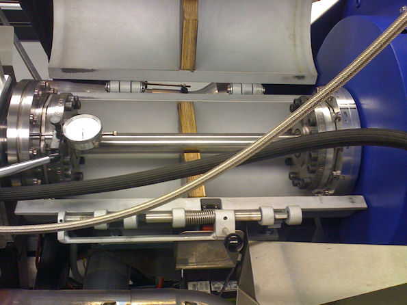
AVL Dyno Input System
In order to allow rapid installation and removal of test engines, ECR Engines acquired an adapter which could be fixed rigidly in place relative to the AVL absorber, thereby avoiding the need to disturb the critical flexure alignment during engine installation and removal, while at the same time extending the distance between the absorber and the engine so as to allow the use of the complete race-car exhaust system in the cell.
This original adapter, which proved to be extremely unreliable, consisted of a steel housing mounted rigidly to the floating cell floor to which the AVL absorber is mounted. The housing contained a 3-inch diameter shaft having an 8.5-inch diameter flange at the dyno-end to attach to the AVL flexure, and at the engine end, a beefy 2-inch OD external spline made from Maraging-300 steel hardened to 62 HRc. A modified bellhousing bolts to the adapter and provides the mounting interface for the rear of the engine. The coupling between the engine's crankshaft and the adapter was accomplished by a primitive "torsional absorber" which relied on the elastic properties of a few internal rubber bits, and which mated with the huge spline on the adapter shaft. This system is pictured below (left side of picture).
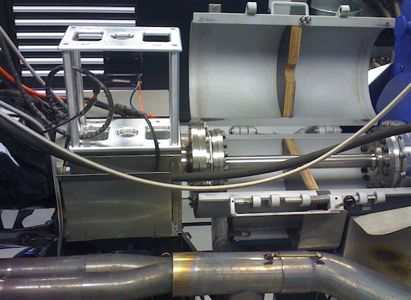
AVL Dyno Adapter
The unreliability of the original adapter was severely compromising the availability of the active dyno cell, and therefore impacting the progress of several critical engine development programs. In as little as 3 hours of simulation testing, the adapter would experience one or more failures including: (a) destruction of the expensive, precision bearings which carry the adapter shaft, (b) resultant damage to the adapter shaft and / or housing; (c) destruction of the rubber-bits in the "torsional absorber"; (d) severe fretting of the massive 2" drive spline and mating female spline, contaminating the entire adapter area with abrasive iron-oxide dust.
Early in 2010, ECR Engines contacted EPI to discuss potential solutions for these problems. We did some analysis of the existing system and identified five major design flaws. One of those flaws was the existence of a system first-mode resonant frequency at approximately 2500 engine rpm (assuming 4th order excitation) which was the suspected cause of a host of other problems.
With this analysis data in hand, we designed a new system which would solve all 5 of the identified problems. The new system would use an adaptation of a torsional isolation system we have used successfully in aircraft engine applications, along with a highly-modified version of the original housing, a highly-modified version of the original 3-inch internal adapter shaft, a modified bellhousing, and a completely new bearing and lubrication system.
We presented this system design and supporting calculations to the ECR Engines engineering staff and after some discussion, they asked us to complete the design AND to build them a prototype of the new system.
In early June 2010, we went to the ECR facility and installed our new adapter system in the active dyno cell. The first time an engine was fired on the new system, everyone commented on how much quieter the environment was compared to all the hammering and clattering the old system produced. One test engineer commented that he could now hear engine noises that had never been possible to hear before.
The EPI Adapter System has apparently solved the reliability problems. The new system (a) moved the problematic resonant frequency down to approximately 700 engine rpm, (b) solved the bearing failure problems, (c) eliminated the primitive rubber absorber, and (d) nearly eliminates the spline fretting. The active cell has been in nearly-constant use with this system since early June, 2010 and, as of this report (November 2010) has survived almost 200 million stress cycles and at least one engine explosion.
As part of this project, EPI provided ECR Engines with a complete set of 3D-CAD models, engineering drawings and process sheets for every component in the system, as well as a detailed, illustrated assembly / disassembly manual. We worked with the ECR engineering staff to develop a "normal maintenance" schedule, and EPI is continuing to make modifications to the system to accomodate other engine packages and instrumentation systems.
(UPDATE 1: Since the installation of this engineered adapter system, ECR Engines has installed a second active dyno cell which also uses our adapter system. As of June, 2014, the adapter system described here has been in constant service in both ECR active dyno test cells, with no problems or failures, and each of the adapter systems are rebuilt as a matter of policy after 500 million cycles.)
(UPDATE 2: In October 2014, EPI was commissioned to design and build the hardware needed to install a highly-sensitive torque sensing element into the system. In a very short time, EPI designed the new subsystem which, in addition to meeting all the requirements, also replaced the delicate (and expensive) flexure joints and AVL titanium driveshaft components with an entire coupling system that is more robust and eliminates several troublesome resonant frequencies as well. We built, delivered, installed and tested this new system in less than 6 weeks. It has now been in successful, full-time operation for several months.)
(UPDATE 3: As of the end of the 2014 NASCAR season, these engines had reached the vicinity of 890 HP at around 9000 RPM, and the gear rule limited their on-track speed to roughly 9500 RPM. Peak torque was up to nearly 540 lb-ft (BMEP of 227.5, torque ratio of 1.51).
It is shameful that this engine configuration, an amazing combination of power, reliability and clever development, has been legislated out of existence by the NASCAR braintrust.
For the 2015 season, in the stated interest of "reduced cost" and "better racing", these geniuses decreed that the 2015 Cup engines will be fitted with a "Tapered Spacer" between the throttle body and the intake plenum. This spacer amounts to little more than a fancy restrictor plate, which limits the amount of air that the engine can ingest.
That rule change immediately reduced the engine power to roughly 725 HP. And while the NASCAR bureaucrats blather on about "reducing the cost of racing", this rule change has required yet another vast expenditure of R&D money to develop a new engine package (combustion chamber, ports, manifold runners, plenum configuration, cam profiles, valve springs, etc. etc. etc) to optimize the performance of this new (different) engine package.
(Good thing I don't have a NASCAR driver license anymore; remember how Hamlin was nearly beheaded for saying on camera that the Gen-5 cars still needed more development?)
