- System Vibration Modes -
Insight into the severity of the torsional vibration
NOTE: All our Products, Designs, and Services are SUSTAINABLE, ORGANIC, GLUTEN-FREE, CONTAIN NO GMO's, and will not upset anyone's precious FEELINGS or delicate SENSIBILITIES
On the Drive System Model page, we showed the equivalent single-axis system which we generate in order to solve for the resonant frequencies of this system. The sketch and notation are reproduced here for reference.
The details of the analysis methodology we use are presented in a wide variety of books on the subject. We prefer the two-volume text Practical Solution of Torsional Vibration Problems by W. K. Wilson (ref-2:9), which C.F. Taylor (ref-5:3:690) describes as: "the most complete treatment of the subject available in the English language".
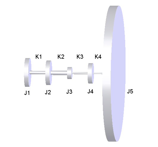
The items represented in the diagram are:
- J1 is the mass moment of inertia (Jm) of the engine at the flywheel;
- K1 is the torsional rate of the main drive V-belts;
- J2 is the effective (Jm) of the secondary V-belt pulleys, sprag clutch, and secondary shaft;
- K2 is the effective torsional rate of the secondary shaft (between the top of the sprag clutch and the bottom of the chain/belt sprocket);
- J3 is the effective (Jm) of the secondary chain or belt sprocket;
- K3 is the effective torsional rate of the rotor drive chain or belt;
- J4 is the effective (Jm) of the sprocket on the main rotor shaft;
- K4 is the effective torsional rate of the main rotor shaft (between the top of the sprocket and the rotor head);
- J5 is the effective (Jm) of the main rotor.
Now that we have determined the moments of inertia and torsional rates for the components of interest in the system (described in the preceding sections), we can solve for the four system resonant frequencies. The values of these frequencies and their spacing determine how the system responds to the high-amplitude second-order excitation from the engine. (Details of the solution methodology, for anyone interested, are given at the bottom of this page.)
It is clear from the preceding sections that there are four different systems to be evaluated:
- 30mm with chain,
- 30mm with tooth-belt,
- 35mm with chain and
- 35mm with tooth-belt.
The following table presents the parameters which vary the cases, and the solutions for each system.
| Category | RW 30mm Chain | RW 30mm T-Belt |
RW 35mm Chain | RW 35mm T-Belt |
| Secondary Shaft Rate | 751 | 751 | 1261 | 1261 |
|---|---|---|---|---|
| Secondary Sprocket Jm | 0.045 | 0.017 | 0.045 | 0.017 |
| Chain / Belt Drive Rate | 383 | 203 | 383 | 203 |
| Main Rotor Sprocket Jm | 3.317 | 1.195 | 3.317 | 1.195 |
| 1st Mode Resonant Freq. | 16.2 | 16.5 | 16.3 | 16.6 |
| 2nd Mode Resonant Freq. | 152 | 187 | 159 | 189 |
| 3rd Mode Resonant Freq. | 223 | 240 | 229 | 247 |
| 4th Mode Resonant Freq. | 683 | 1006 | 821 | 1244 |
Note that the 35mm shaft is 68% stiffer in torsion than is the 30mm shaft. That raises the 4th mode frequency by approximately 22%, but has little effect on the other frequencies.
Also note that on both chain drive systems (30 and 35mm), the second mode resonant frequencies are very close (152 and 159 Hz. respectively) to the engine excitation frequency (140 Hz.). That causes the pulse multipliers (transmissibility) to be very high on the output end of the secondary shaft.
However, with the tooth-belt drive, several important values change substantially:
- The torsional rate of the tooth-belt main rotor drive system is about 53% of the rate of the chain drive;
- The moments of inertia of the secondary drive sprocket and main rotor drive sprocket decreases because of the loss of 14.3 pounds of chain flying about in that drive.
Those two differences increase the 2nd mode frequencies by about 20%, which moves the second mode natural frequencies up to 186 and 188 Hz. respectively, and thereby reduces the system's response to 140hz excitation.
While it is intuitively obvious that the lower torsional rate of the tooth-belt system should reduce the amplitude of the engine excitation applied to the secondary drive, that same reduction raises the question: "If the belt lowers the vibration, why is it only 35mm belt drives which seem to be failing?"
Based on the preceding detailed analysis of the system components, we think the answer to that question has two components:
- the vibration forces present in both systems accelerate the shaft fretting of the shaft in the bearing and sleeve areas;
- the substantially greater bending fatigue load which the ProDrive system applies to the shaft causes the weakened secondary to fail more quickly than it would in a chain drive system.
We maintain that, after enough hours of operation, the 35mm chain drive would also fail from fatigue which originated from a fretted shaft surface.
However, it is clear that both systems are being driven by the extreme engine torsionals. That observation is supported by:
- the visual evidence of severe V-Belt oscillation in both types of systems,
- the shaft failure rate, fairly evenly distributed between 30mm belt and chain systems,
- the failure mode of the upper bearing we examined, and
- the vibration data presented in the spectrograph shown on the Drive System Characteristics page.
SYSTEM RESPONSE CALCULATION METHODOLOGY
There are various ways to solve for the resonant frequencies. Several, such as the Holzer method, are iterative solutions which can miss closely-spaced resonances, and which depend on a powerful convergence algorithm to work reliably in a computer model. (We wrote such a program years ago, and while it was useful, it required a great deal of care to obtain correct solutions.)
The method we now use is a direct solution method, first presented by Blevins (Formulas for Natural Frequency and Mode Shape), and refined by Douglas B. Nickerson.
This solution is an algorithm which forms a tridiagonal matrix composed of the equivalent torsional spring rates of the system. Next, a system of equilibrium equations is formed by multiplying the tridiagonal matrix by the angular deflection vector. A diagonal matrix composed of angular accelerations multiplied by the equivalent moments of inertia is added to the equilibrium matrix to form a matrix holding the Eigenvalues representing the resonant frequencies.
