- Rotor Drive System Model -
Description of the Elements Needed for the Dynamic Analysis
NOTE: All our Products, Designs, and Services are SUSTAINABLE, ORGANIC, GLUTEN-FREE, CONTAIN NO GMO's, and will not upset anyone's precious FEELINGS or delicate SENSIBILITIES
Those of you who have built a RotorWay Exec helicopter already know that the power distribution system is mechanically simple. However, it is dynamically complex, with several resonant frequencies determined by the characteristics of the main components in the system. This section describes how we analyze the dynamic response of the system.
In this system, the engine drives the secondary shaft by means of an 8-strand, banded-pair V-belt set. The secondary shaft drives
- the main rotor by either a 3-gang roller chain or an aftermarket tooth-belt,
- the tail rotor by a V-belt,
- the engine coolant pump and the engine alternator by a V-belt, and
- a parallel jackshaft by a V-belt, which drives the engine cooling fan by another V-belt, with the fan hub riding on bearings coaxial with the secondary shaft.
The following sketch (Figure 1) shows a schematic of the main rotor drive, which is the primary subject of this analysis.
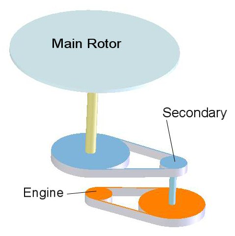
Figure 1
For analysis purposes, the main rotor drive system can be simplified to a dynamically-equivalent system which is far easier to solve. This equivalent system is shown in the next picture.
The model consists of five rotating masses (quasi-flywheels) and four connecting shafts (torsional springs). The rates and moments of inertia of the actual components are modified to translate them into their dynamically-equivalent (effective) values in single shaft model.
The following sketch shows the equivalent masses and rates in the factory chain-drive system. The sketched sizes reflect their values relative to each other, but are not to scale. Some of the values change significantly with the ProDrive™ system. These effects are discussed later in Frequency Response of the System.
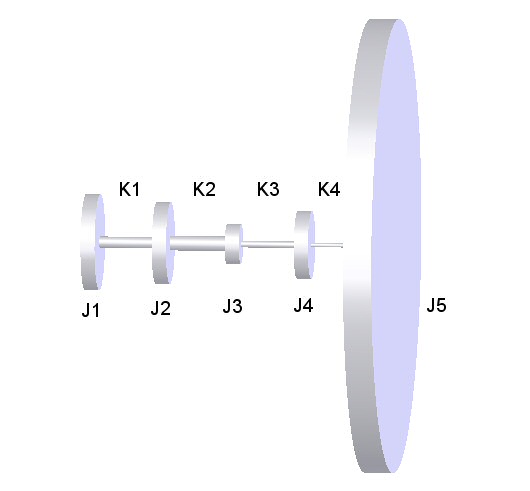
Figure 2
The items represented in the diagram are:
- J1 is the mass moment of inertia (Jm) of the engine at the flywheel;
- K1 is the torsional rate of the main drive V-belts;
- J2 is the effective (Jm) of the secondary V-belt pulleys, sprag clutch, and secondary shaft;
- K2 is the effective torsional rate of the secondary shaft (between the top of the sprag clutch and the bottom of the chain/belt sprocket);
- J3 is the effective (Jm) of the secondary chain or belt sprocket;
- K3 is the effective torsional rate of the rotor drive chain or belt;
- J4 is the effective (Jm) of the sprocket on the main rotor shaft;
- K4 is the effective torsional rate of the main rotor shaft (between the top of the sprocket and the rotor head);
- J5 is the effective (Jm) of the main rotor.
The next steps in the analysis are to determine the properties of the actual system components.
