- Lubrication Systems -
Characteristics of Pumps, Pans, Tanks, Coolers, Filters, Plumbing
--- AND insight into some MYTHS and CLAIMS ---
NOTE: All our Products, Designs, and Services are SUSTAINABLE, ORGANIC, GLUTEN-FREE, CONTAIN NO GMO's, and will not upset anyone's precious FEELINGS or delicate SENSIBILITIES
Introduction
ThIs discussion addresses the properties, requirements, and operation of the lubrication systems found in contemporary piston engines. The following few paragraphs describe, in general terms, the operation of a contemporary engine lubrication system. The specific item descriptions are mostly based on the SBC / BBC / LS engine architecture, but do apply in general to other designs. (NOTE: EPI does not sell oil pumps.)
The most common system layout has a single pressure pump that is driven directly by the engine, either by gearing from the camshaft, or in more contemporary engines, driven directly by the engine crankshaft.. The pump draws oil from the bottom of a reservoir ("sump") through a coarse screen and pickup tube at the bottom of the engine, and discharges the oil to the engine. The volume of oil pumped to the engine is roughly proportional to the pump (hence engine) RPM, until the regulator comes into play (more on that later). This type of system is typically referred to as a "wet sump" system.
The discharge from the oil pump is typically delivered to a full-flow oil filter that removes most particulate contamination from the oil, to assure that the bearings and other internal parts receive uncontaminated oil. From the filter, some systems include an oil thermostat that routes some (or all) of the fresh (hot) oil to a heat exchanger ("oil cooler") then back to the thermostat discharge port. The oil cooler and thermostat maintain the oil temperature at a safe level in heavily-loaded engines.
From the filter / cooler subsystem, the pressurized oil flows into the engine where it is routed to the "main oil GALLERY " (not "galley" - a galley is the kitchen on a ship). That gallery is typically a passage drilled in the block that runs longitudinally from front to rear.
From that gallery, pressurized oil flows through smaller drilled passages ("main bearing feeders") to the main bearing bores in the block. The main bearing inserts have oil feed holes in them that align with the holes where the main bearing feeders break into the main bores. Through those holes, oil is delivered to the main bearing surfaces, where it lubricates and cools the main bearings and main crankshaft journals. The operation of hydrodynamic engine bearings is described in detail HERE.
There are drilled passages in the crankshaft that go from the crankshaft main bearing surfaces out to the conrod bearing journal surfaces. Some of the pressurized oil that is delivered to the main bearings is routed through these drilled passages to lubricate and cool the conrod bearings. These drilled passages can be seen in several photos in the Crankshaft Design section of this site.
In pushrod OHV engines, typically there are transverse passages drilled in the block that intersect the main bearing feeder holes in the main bores and go upward at an angle (to avoid intersecting the main gallery). Those passages feed oil to the camshaft bearings. This arrangement, in which the main bearings get the first-available oil supply, is known as "priority-mains oiling".
There are also longitudinal sub-galleries that feed off the main gallery and run lengthwise along the block and partially intersect with the cam follower bores. Those passages deliver oil that lubricates the cam followers ("lifters") and deliver pressurized oil to the hydraulic lifters (if the engine is so equipped). Typically, the lifters then feed oil into the hollow pushrods where it it delivered upward onto the rocker arm pivots, pushrod sockets, valve springs, and valve stems.
In overhead camshaft engines (OHC), there are various drilled passages that deliver pressurized oil to the cylinder head where it feeds the cam bearings, cam follower bores and cam lobe interface surfaces, rocker arm bearings, rollers, pivots, valve springs and valve stems as appropriate, and to any hydraulic lash adjustment mechanisms that may be in place on a given engine.
Eventually, all this pressurized oil flows out of the tight spaces to which it was delivered and runs through passages and along surfaces back downward toward the sump. However, on the way back to the sump, a lot of the runoff oil collides with the rapidly-moving rotating and reciprocating parts. That collision creates a massive cloud of splash-oil ("windage") that flies onto cylinder walls, piston surfaces, wristpin bores, cam-to-lifter interfaces, and other passively-lubricated joints.
The unfortunate byproduct of that splash / windage lubrication is that the drain oil is thrashed into a frothy air-oil mixture, which does not lubricate well at all. Fortunately, most of the air separates out of the mixture that is at the surface of the oil in the sump. The oil pump feeds from a pickup at the very bottom of the sump, thereby ingesting the least-aerated oil for its next pass through the engine.
There are active de-aeration systems in some high-performance engines that will be discussed later.
General Oil Pump Characteristics
In any piston engine, the oil has two primary functions: to lubricate the moving parts (obviously) and to cool (pistons, rings, bearings, valve springs, and other moving parts). Proper engine operation depends on an adequate, continuous supply of oil, which requires a good, properly sized pressure pump.
A good pressure pump, whether it is a gear-style, gerotor-style, or a lobe-style, delivers a relatively constant volume of oil for every revolution of the pump.
The flow rate of oil delivered by a pump, typically expressed as Gallons Per Minute, GPM, or Liters per Minute, LPM, increases almost linearly with pump RPM, without regard to delivery pressure.
As pressure increases, there will be a small decrease in volume pumped at any given RPM because of internal leakage paths inside the pump.
The pump sizing for a given engine is usually determined by the delivery volume required to maintain adequate oil pressure in a hot engine with hot oil, at idle speed.
However, the nearly-direct relationship between output volume and pump speed results in a huge excess capacity at higher engine speeds. That problem is solved by a device that prevents excessive oil pressure at high engine speeds, by short-circuiting some portion of the pressure-pump delivery volume back to the inlet side of the pump. That device is the pressure regulator valve (also called a "pressure relief valve"), discussed in detail later.
The term "effective orifice" means the equivalent flow area of the combined sizes of all the "holes" for oil to flow through in the engine, including bearing clearances (conrod, mains, cam bearings), cam-follower clearances, cam follower lubricator nozzles, rocker-arm orifices, spring and piston cooling jets, etc.
The delivery pressure at a given pump speed and oil viscosity is determined by the size of the effective orifice to which the pump is delivering oil.
It should be obvious that when the effective orifice gets larger, at a constant pump speed and viscosity, the pressure will decrease for the same delivered flow (GPM)..
For example, when a cold engine first starts, all the clearances are relatively small and the oil is cool, so the oil viscosity is relatively high ("thick" oil). That causes the oil pressure to be high at idle speed, and the idle oil pressure will usually be determined by the regulator valve setting. As the engine reaches operating temperature, the clearances will increase significantly (especially in an aluminum-block engine) and the oil viscosity will decrease.. Therefore, at idle, because the effective orifice has increased, coupled with the decrease in oil viscosity, the oil pressure at idle will decrease and allow the pressure regulator valve to close completely. At that point, the idle oil pressure is determined by the idle-speed delivery capacity of the pump.
Conversely, when the delivered flow increases to a fixed effective orifice, the delivered pressure will increase. For example, when the engine RPM increases off idle, the pump flow increases, causing the delivered pressure to increase, until the pressure required to push the total pump flow through the effective orifice reaches the setting of the regulator valve. At that point, the regulator valve opens just enough to maintain the pressure at that preset level. In order to maintain a nearly-constant oil pressure.
Furthermore, although positive displacement pumps are fairly insensitive to changes in the viscosity of the fluid inside the pump, that is not the case with respect to the flow through a given effective orifice. At a fixed delivery pressure, the flow through a given effective orifice size will increase as viscosity decreases. That has the effect of increasing the effective orifice.
For a complete discussion of how engine bearings work and why they have amazingly-low frictional losses, read THIS PAGE
Gear Pumps
Gear pumps consist of a pair of meshing external-tooth gears, the first of which is driven by a power source. The other gear rides on an idler shaft, and is driven by the first gear. The two meshed gears are enclosed by a housing with a gear cavity that closely-surrounds the two gears.
Figure 1 shows a cutaway of a typical gear pump. In this pump, the lower gear rotates clockwise as shown.
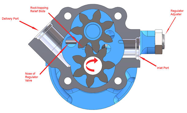
Figure 1: Example of a Gear-Type Pump
As the two gears rotate, the teeth come out of mesh on the inlet side, creating a larger volume in that cavity. That larger volume causes the pressure to decrease, drawing in some new oil. As the gears rotate, oil is trapped in the spaces between the teeth by the clowely-fitting housing, and is moved by the rotation of the gears into the output (delivery) cavity. When the teeth come into mesh in the delivery cavity, that causes a small reduction in the cavity volume, which forces some of the oil in that cavity to flow out the delivery port.
The tight clearances between the housings and the gears (typically 0.001-0.002 inches), as well as between the meshing gear teeth, coupled with the relative motion between the meshing teeth and berween the gears and the housings, create a very effective dynamic seal that prevents all but a miniscule amount of back-leakage. Thus for every rotation of the gears, a fixed volume of oil is transferred from the intlet port to the delivery port.
As mentioned above, the typical sizing of an engine oil pump so as to provide sufficient oil pressure at a hot-engine idle, results in a massive over-capacity of the pump at higher RPM. That problem is solved by the inclusion of a pressure regulator valve into the pressure pump housing.
The pressure regulator typically consists of a spring-loaded plunger that moves in a tightly-clearanced bore in the housing. Figure 2 below shows a cross-section of that arrangement. The blue component is the regulator valve, which is loaded by the spring up against its low-pressure stop (the "nose" of the valve).
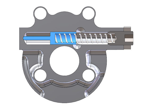
Figure 2: Cross-Sectional View of a Typical Pressure Regulator at Low Delivery Pressure
The left end of the valve cavity (in Figure 2) is exposed to pump delivery pressure through the port shown in Figure 1, where the "Nose of :Regulator Valve" is shown. The delivery pressure creates a force on the face of the regulator valve (pressure x valve face area). That force is opposed by the regulator spring, which has a preload established during assembly and sometimes adjustable within a limited range by the allen-screw-and-locknut mechanism shown in Figures 1, 2, and 3.
As delivery pressure increases, the force on the regulator valve increases until it equals the spring preload, at which point the valve begins to move to the right, compressing the spring until the force exerted by the deflected spring equals the oil pressure force on the face of the valve.
When the delivery pressure creates sufficient force to allow the valve to move to the right enough to begin to uncover the "short circiut" ports (the two holes shown in Figure 2 to the right of the end of the regulator valve), some of the pump delivery volume is routed back to the inlet cavity of the gear pump. That increases the effective orifice to which the pump is delivering oil, thereby maintaining a somewhat constant pressure.
Figure 3 shows the regulator valve at its full displacement, short-circuiting the maximum amount of flow back to the inlet cavity of the pump.
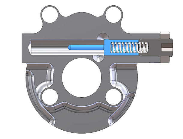
Figure 3: Regulator Valve at Maximum Short-Circuiting
Because the regulator spring provides a resisting force that varies with the length of the spring, then the delivery pressure that causes maximum movement of the regulator valve will be higher than the pressure that causes the valve to just-open the bypass ports. That will cause a small non-linearity in the regulated pressure at high pump output volumes.
This short-circuiting system has a significant benefit to the operation of the system, because it substantially reduces the volume of oil that must flow up through the inlet plumbing at high pump output values. That reduces the probability of cavitation in the inlet system, which can destroy a pump and severely limit the flow of oil to the engine. (More on that below).
Gerotor Pumps
The ‘gerotor’ pump consists primarily of an internally-toothed outer rotor, an externally-toothed inner-rotor, a pressure regulator valve, and the housing set that contains and positions those components. Figure 4 shows a cutaway of this style of pump.
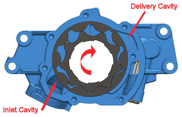
Figure 4: Cutaway View of an LS Gerotor-Style Pump
The inner rotor has trochoidal-profile lobes, and the profile of the internal lobes on the outer rotor is developed from the inner rotor profile. Ths inner rotor has one less lobe than the corresponding outer rotor. The centerlines of the two rotors are not coincident, but instead operate at a fixed offset from each other, established by the geometry of the housing.
The shape of the lobes is such that the surface of each lobe is at a tangent to and almost touching the surface of the lobe opposing it (0.001 to 0.002 inches clearance) and is nearly in sliding contact with it. As with a gear pump, the axial clearance between the rotors and the faces of the housing are also in the 0.001 to 0.002 range. These very small clearances generate an effective dynamic oil seal between the two elements and between the rotors and the housings. Those seals prevent backflow and loss of pump efficiency.
As the two rotors turn (clockwise shown in Figure 4), the cavity volume between the two rotors increases as it moves across the inlet ports, and then decreases as it moves across the outlet (delivery) ports.
Figure 5 below shows the pump housing without the rotors, to provide a better picture of the inlet and delivery cavities. Note how there is a fairly large wall at the top between the inlet and delivery cavities. The width of that cavity extends across the angular portion of the rotor travel in which there is essentially no change in the volume of the space between the inner and outer rotors (shown in Figure 4).
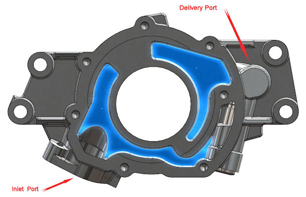
Figure 5: LS Gerotor-Style Pump with Rotors Removed
It is also noteworthy that the best gerotor pumps have mirror images of the inlet and delivery cavities in both walls of the housing. The outline of that cavity-mirroring is shown in Figure 6, an external view of the entire pressure pump from a GM LS wet sump engine.
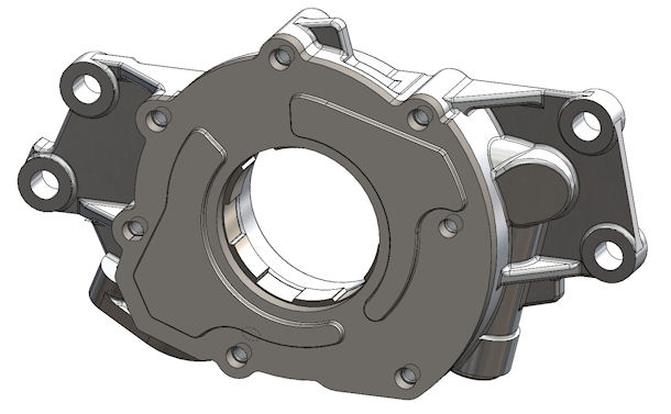
Figure 6: Complete LS Oil Pump
Figure 7 shows a cutaway of the regulator system in this gerotor pump. It operates in the same manner as the regulator valve described in the gear pump section above.
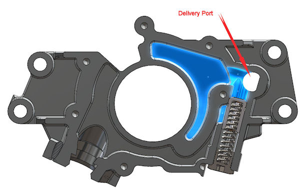
Figure 7: Cutaway View of an LS Pump Regulator
A major claimed advantage of gerotor pumps over gear-pump designs is the reduced pressure pulsations in the delivery port. Also, the intake and delivery ports of a gerotor pump open and close over much larger periods of angular rotation than gear pump designs. That property is less likely to introduce turbulence and cavitation at higher engine speeds.
However, a major disadvantage of gerotor pumps is the fact that they are more susceptible to being jammed by loose engine debris. That issue can be overcome by an effective, but low restriction, filtering system on the inlet pickup.
Another (potantial) disadvantage is that, for high efficiency, the pump diameter needs to be quite large (for example, the LS engine pump shown above). Pumps with small diameter, long rotors have more difficulty completely filling the pumping cavities at higher RPM when compared to large diameter, thin rotor pumps. Examples of these small-diameter, tall rotor pumps can be found in the MGA / MGB engines and certain Subaru engines. Automatic transmissions typically use large-diameter, thin rotor pumps that are capable of high flows and output pressures well above 300 psi.
As engines have evolved away from distributor-ignition and into ECU-controlled, crankshaft-position triggered ignition systems, oil pumps running directly from the nose of the crankshaft have become commonplace.
Pumping Efficiency
There are several parameters that contribute to efficiency in pumps. Naturally, the clearance between the gears (rotors)
influences bypass leakage. Similarly, the side (axial) clearances between the housings and the rotors also influence bypass leakage.
Tighter OD and side clearances mean less bypass leakage as the pressure increases, thus greater pump efficiency.
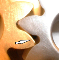
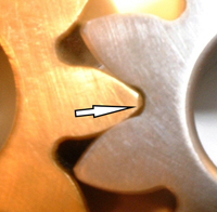
Figures 8 & 9:: Detail of the Root-Trapping Phenomenon
An often-ignored efficiency in gear pumps is the elimination of "root-trapping". These two pictures (Figures 8 & 9) show how "root trapping" wastes power.
The picture to the left shows one tooth of the bronze gear (turning counterclockwise) just entering the root cavity of the steel gear, and shows how large the root volume is at this point. The picture to the right shows how small that root volume becomes as the gears continue to rotate.
If that root volume of oil doesn’t have an escape path, the pump experiences a noticeable binding at every mesh, wasting power. Quality pumps have a clever root-trapping eliminator built into every stage.
Another important component of engine oil pump efficiency is the design of the bypass-relief valve system. Once the delivery pressure reaches the set point, the relief valve should maintain that pressure as RPM increases beyond that point. If the delivery pressure rises significantly with RPM, the relief valve is poorly-designed and is causing you to waste power pumping oil.
Calculating Gear Pump Flow
THIS EQUATION provides an estimate of the flow capacity of a GEAR PUMP as a function of gear size and pump RPM.
Q=(N*W*C*(D-C))/73.48
where
Q=pump flow in GPM
N=speed (pump rpm)
W=gear face width (inches)
C=center distance between gears (inches)
D=gear OD (inches)
Expanding that expression out into word form produces:
Flow (gpm) = (rpm x gear width x center distance x [gear OD - center distance] ) / 73.48
Here is an example.
Suppose you have a gear pump with 1.25" wide, 1.499 inch OD gears operating at a center distance of 1.667 inches. Suppose that pump is geared to the engine at a ratio of 5/8 of crankshaft speed, and the engine idles at 900 rpm, making the pump speed 563 RPM (900 x 0.625) at idle. Therefore the estimated delivery flow of that pump in those conditions is:
Flow = 563 (rpm) x 1.25 (width) x 1.1667 (center distance) x (1.499 - 1.667) / 73.48
That resolves to 5.31 gallons per minute. A typical aluminum LS engine requires approximately 2.5 GPM at a hot, 900 rpm idle, so this example pump is a bit oversized for the engine.
Calculating HP Required by a Pump
THIS EQUATION provides a means to estimate of the POWER REQUIRED TO DRIVE A PUMP that delivers a known flow at a known output pressure.
Pumping HP = flow (gpm) x pressure (psi) / (efficiency x 1714)
For those wondering about the derivation of that Pumping HP equation, everyone knows that there are (a) 12 inches in a foot, (b) 231 cubic inches in a gallon, and (c) 33,000 ft-lb of work per minute in one HP.
SO:
gallons per minute x pounds per square inch x cubic inches / gallon = inch-lbs per minute;
33000 foot-pounds per minute x 12 inches per foot = 396,000 inch-pounds per minute
396000 / 231 = 1714.3
As an example, a 75%-efficient pump delivering 30 gpm at 85 psi would consume approximately 2 HP (1.984).
(30 x 85) / (1714 x 0.75) = 1.984.
The Argument About "Power to Drive a Pump"
In the course of working with lots of different engine projects, we often hear the suggestion that engine power can be increased by the use of a "better" oil pump. Implicit in that suggestion is the belief that a "better" oil pump has higher pumping efficiency, and can, therefore, deliver the required flow at the required pressure while consuming less power from the crankshaft (but MORE from your wallet). While that is technically true, the magnitude of the improvement is surprisingly small.
Recall the HP solution just above that showed a 75% efficient pump at 85 psi requiring 1.984 HP to drive it. Now, suppose some slick salesman convinces you to shell out a boatload of money for a pump that is claimed to be 95% efficient, because he says it will increase your engine power output.
If you calculate the power to drive that new big-bucks pump, you get:
(30 x 85) / (1714 x 0.95) = 1.566 HP.
WOW !!..... A net gain of less than 7/16 of a HP (0.418 to be exact).
Can your dyno even measure a 1-HP difference accurately and repeatably?
Bypass Oil Recirculation
Some pump manufacturers like to claim that a pressure regulator that recirculates the bypassed pressurized oil back to the inlet of the pressure pump causes the oil temperature to increase. Well, technically that is true. The problem is that the temperature increase due to recirculation is so small that it is difficult to measure accurately.
Those manufacturers who criticize recirculation will claim their products are superior because, instead of recirculating the bypass oil back into the pressure pump inlet, they pump it back to the sump (or to the oil tank in a dry-sump system)..
HOWEVER, sending the bypassed oil back to the sump (or tank) creates an even bigger problem: The output of the pump at high RPM can be 30 - 40 GPM or more, while the engine may require only 8 - 12 GPM. That means that the pump will be bypassing at least 18 GPM through the pressure regulator valve to maintain the set-point oil pressure.
If the bypass oil does not recirculate to the pump inlet, then the full pump volume (30 - 40 GPM or more) must flow from the sump (or tank) to the pump inlet through the inlet line, with only atmospheric pressure (at best) to move it. The reality is that it typically can't be done without reducing the pressure in the inlet line to below the vapor-pressure of the oil. That will cause pump cavitation, inlet hose collapse, aerated lube oil, and all the engine problems that follow those problems.
Gear Pump Advantages
Several manufacturers claim that their gerotor-style pumps produce more "efficient" oil pressure with less "pulsing". Here, we have more marketing claims without any data to substantiate them. Depending on the style of gerotor pump, there can be just as many pressure pulses per pump revolution as produced by a gear pump. For example, the OEM gerotor-style pump which is in every wet-sump GM LS-series engine, has 9 lobes on the inner rotor. That produces the same number of pulses per pump revolution as a 9-tooth gear pump. However, the rate of change of the pressure pulses in a gerotor pump is smaller.
AND, it has been proven time and time again, in various forms of competition engines, that a gear-style pump is far more forgiving of debris than a gerotor pump.
DRY SUMP SYSTEMS
The generally-accepted description of a "dry sump system" is a lubrication system in which the oil that is supplied by the pressure pump drains off the engine as a frothy, thoroughly-mixed air-oil suspension into a relatively shallow, low-capacity, sump that is frequently coutoured to the rotating-assembly. In this system, there are several scavenge pump stages that pump the aerated oil from the "dry" sump and into an oil tank that has the dual-assignment of
- storing the major amount of the engine oil supply, and
- de-aerating the mixture being returned by the scavenge pump(s).
The system pressure pump draws its supply from that oil tank. The sump is not really "dry", but in operation, it contains very little oil.
The reasons for using such a more-complex and heavier system include:
- lowering the engine in the vehicle, thereby lowering the vehicle CG,
- providing an uninterrupted oil supply at high horizontal (cornering) g-loads which, in a wet sump system, would cause the oil to pile up against the outside sump wall, causing the surface of the oil to be at a significant angle from the horizaontal, and potentoially uncovering the pump pickup mechanism, and
- providing an increase in engine power at high RPM by reducing windage losses and providing a lower pressure ( "vacuum" in the engine sump (discussed below).
The following diagram (Figure 10) shows a schematic of a typical, well-done dry-sump engine oil system.
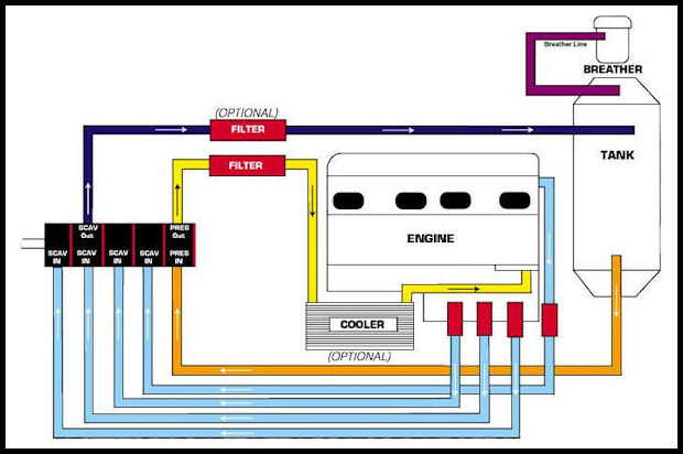
Figure 10: Typical Dry Sump System Schematic (Courtesy of MOROSO)
The operation begins with the pressure stage of the pump. It draws oil from the bottom of the oil tank (orange line) and pumps that oil to the filter (yellow line). The (yellow) line from the filter next goes to the oil cooler, which may or may not have an oil thermostat controlling the flow through it. From the oil cooler, the oil goes to the engine inlet port (yellow line again) where it is internally routed to the crankshaft and camshaft bearings, cam followers, chain tensioners, valvesprings, piston cooling jets, and other engine components needing lubrication and / or cooling (as described in more detail above).
After passing through the various engine components, the oil flows into the sump at the bottom of the engine. From the sump, the scavenge stages of the pump retrieve a dreadful mixture of highly-aerated oil (blue lines) showing three lines in from the sump and in this particular diagram of a V-type engine, one scavange line from the valley. The scavenge pump stages collect that scavenged flow into a (black) line that goes to a scavenge oil filter and then to a centrifugal and boundary-layer air-oil separation system in the oil tank. The air that is extracted from the scavenge oil exits the system through the breather (violet line).
NOTE that locating the oil cooler in the line from the scavenge-outlet to the tank severely limits the effectiveness of the cooler because it is trying to transfer heat from a highly-aerated mixture.
Some pumps (Auto-Verdi, Dailey, and others) have an optional centrifugal air-oil separator integrated into the rotating mechanism of the pump itself.
The following picture shows a typical 4-stage dry sump oil pump. It is intended to be mounted on the exterior of the engine and is driven typically by the crankshaft using one or more high-capacity tooth belts. The pump shown below is a high quality-but-affordable 4-stage pump with a rigid, double-blade mounting system, available from NRC.
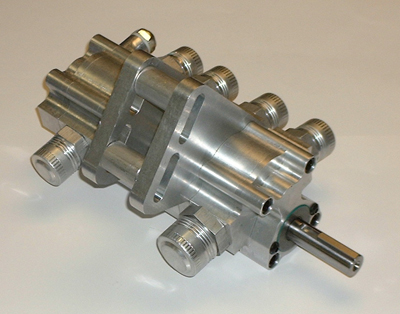
Figure 11: Four Stage External Dry Sump Pump
The following picture shows a different pump mounting system on the engine block of a GM-LS engine.
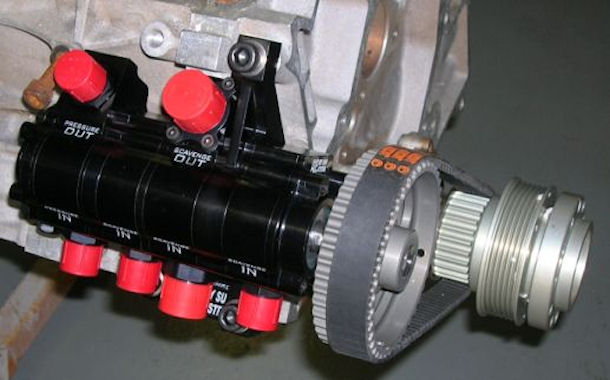
Figure 12: Typical External Pump Mounting Arrangement
Figure 13 below shows a rigid double-blade mounting system on an EPI engine. This system has a double-belt drive that has fences between the belts to prevent one failed belt from destroying the other one. We designed this setup to achieve the reliability we want in an aircraft application.
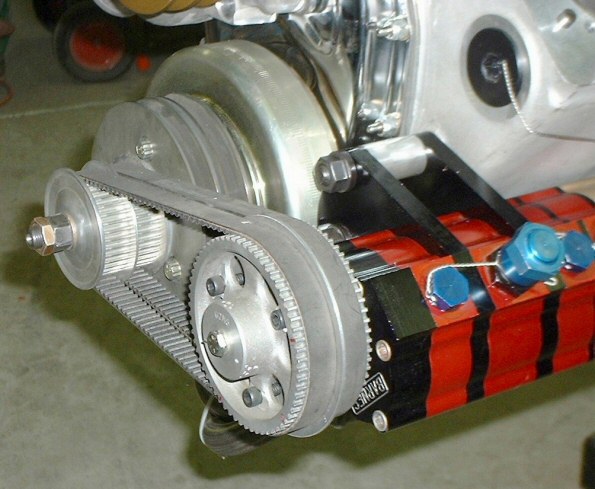
Figure 13: EPI Aircraft-Style External (BARNES) Pump Mounting Arrangement
Here is a list of the requirements of a high quality dry-sump engine oil pump:
- It must deliver the required flow (GPM) of oil to the engine in order to maintain the desired oil pressure throughout the temperature and RPM range, with enough delivery volume to assure the right amount of oil is delivered to parts which are most difficult to lubricate and cool (rod bearings, piston crowns, valve springs),
- It must effectively scavenge the outflow oil from the engine,
- It should be capable of producing a reasonable level of crankcase vacuum (if the engine builder decides to use that technology) for good ring seal and minimized windage losses, and
- It must perform consistently and trouble-free for a long time .
RELIABILITY
Starting with requirement #4, in order to perform consistently and reliably, the pump must first attach to the engine rigidly and not wobble all over the place when the drive-belt loads fluctuate. AND THEY DO FLUCTUATE, at an unexpectedly-high frequency, as a result of the scavence sections intermittently pumping oil at one moment, and air at another. High grade block-mount pumps use a specially-engineered double-mount-blade design (as shown in the picture above) which eliminates the wobble and flex found in single-blade designs.
High quality pumps also use high-strength, high endurance materials (AMS-4150 steel shafts, 6061-T6 aluminum housings, and a high-grade bronze for bushings), ball bearings, molded o-rings, along with precision manufacturing and assembly to assure consistent performance and long life.
CRANKCASE VACUUM
In addition to a measurable reduction in windage losses, a dry sump pump that can establish a suitable level of crankcase vacuum can provide a measurable increase in engine power. There can be no argument that some of the high-end roots-style scavenge pumps do an excellent job of providing good scavenging and high vacuum levels. But gear-style scavenge sections, specifically optimized for high crankcase vacuum, have been demonstrated, both in side-by-side testing and in competition, to provide at least equal and often measurably superior vacuum levels.
What is the advantage to using a large amount of crankcase vacuum in a race engine?
HORSEPOWER; WHAT ELSE?
And it is the cheapest HP you can buy. If you can achieve a crankcase vacuum level of at least 8 inches HG, you will very likely realize an immediate power gain of at least 15 HP (on a V8 application).
If you run a V8 dry sump system with a three stage pump (one pressure stage, two scavenge stages), in most cases you cannot achieve a sufficient level (8 "HG) of crankcase vacuum to achieve that power gain. The extra cost of a four stage pump will net you around 15 HP in most cases.
How It Works
The reduced pressure ("vacuum") in the crankcase is generated by having a substantial excess of scavenging capacity with respect to the engine's oil flow rate. The "vacuum" increases the pressure differential across the ring package, producing an improved ring seal. The improved ring seal allows the use of a low-tension (reduced friction) ring package, yielding a power increase as well. Further, the reduced crankcase pressure dramatically reduces windage losses at high RPM.
Here are a few observations we have made over the years of developing winning race engines. First of all, in most engines, the expected power gains will occur with 8 to 10 inches HG crankcase vacuum. Beyond that point, more vacuum does not generally produce any measurable power gain until (a) you get more than 20 inches HG of vacuum AND (b) you are operating in excess of approximately 8300 RPM.
However, we generally size the systems on our engines to produce around 14 "HG when the engine is fresh. That provides sufficient capacity so that as the engine wears and blowby increases, there will still be sufficient scavenging capacity to achieve the 8"HG minimum, and power does not drop off noticeably.
If you want to run a high level of crankcase vacuum (18 inches HG {mercury} or more), there must be provisions in the engine to supplement the lubrication that used to occur when oil was being thrashed about by the moving parts ("windage"). There will likely be problems with at least wristpin and cam follower lubrication.
The best solution will be the addition of piston oilers and, if your engine has a flat tappet cam, provisions for extra lubrication of the cam lobe-to-lifter interface will certainly be required. If you are trying to achieve over 18 "HG, you will need to install special crankshaft seals (front and rear) which have the sealing lips reversed to hold that higher level.
In order to achieve 8" HG or more, the engine must be well sealed. In order to check for leaks, you should pressurize the assembled engine. You will need an adjustable pressure regulator with a low range (like 0 - 10 psi) air pressure gauge. With the engine completely assembled, cap off the fitting that feeds the oil into the main oil gallery, and cap off the scavenge exit fittings from the pan. Install a pressurizing fitting into one of those caps.
We use 6 to 8 PSI (which is equal to 12 - 16 inches HG) of air pressure to test our 8 - 14" engines. Start with the regulator set to ZERO and slowly add pressure, up to the max test pressure you decide to use, and listen for air leaks. If you hear any and can't pinpoint the source, spray some windshield foamy cleaner in the suspected area with a hand spray-bottle. NOTE: You will get better sealing with the cork rocker cover gasket than with the rubber steel lined rocker gaskets.
You should be aware of a few potential glitches. Some silicone sealers cure differently than others, and most take weeks to cure completely if it is 1/8” or thicker. An uncured bead of silicone sealant will tend to be pushed out when pressure is applied. But if it is not fully cured, it will be sucked into the engine under vacuum conditions. We think the best silicone sealer is the OEM stuff, and the Permatex Ultra-Gray is also a good product. The OEM and Permatex Ultra-Gray tend to cure harder on the exposed areas which makes it a little more resistant to being pushed out or sucked in. However, both these products take a considerable amount of time to cure fully when the bead is thick.
We have found that the softer curing stuff tends to develop leaks after the engine has been placed in service, because it moves around during the race. Recently, we have been experimenting with a two-part silicone, which is similar to two-part epoxy, but looks and feels like silicone and cures for limited use in about 30 minutes, and completely cures in 24 hours. So far, the results are encouraging.
Dry Sump Oil Pans
The pickups in most of the aftermarket pans are horrible. The pickup fittings which are commonly supplied are rectangular boxes with sharp, square corners. Those square corners play havoc with the orderly pickup of scavenge oil and add to the turbulence and aeration which occurs at that end of the system. A good hint about how the pickups should be formed can be seen by examining the pickups provided on OEM wet-sump pumps.
Next, almost all the aftermarket pans use dash-12 scavenge fittings. Common sense says there is more volume inside a given length of a dash-12 hose than in the same length of a dash-10 hose. Using the smaller dash-10 hose causes no meaningful increase in flow losses, but it causes a larger percentage of the hose volume to be filled with oil instead of air. Reducing down to dash-10 scavenge lines will help achieve a higher level of vacuum. You can buy the reducers from the common suppliers such as Moroso.
As far as pan design is concerned, the wider and deeper the pan is, the easier it is to control the thrashing of oil, and the easier it is to scavenge the pan well. We also found that the better the pan design (wider, deeper, with scrapers, louvers, one-way-mesh, etc) the expected gains from a high vacuum will be less. The high-vacuum system will produce the best power increases on engines with shallow pans, which are often required as a result of engine placement restrictions or from chassis construction.
Cavitation
Apart from the accidental ingress of debris, the greatest danger to any design of oil pump, particularly one of the gear tooth design, is that of cavitation. Commonly found in centrifugal pumps also, the presence of this phenomenon and the resulting surface erosion is often confusing to the uninformed.
Cavitation is a complex process that can have any of several causes. For an adequate explanation, it is useful to understand and explore some of the more basic principles of fluid mechanics.
In particular if we consider the case of steady flow along a streamline, it is an established fact that the pressure will decrease as the velocity increases. In the case of a liquid however, this pressure must not drop below that of the vapor pressure of the particular liquid at the temperature under investigation.
If for any reason the pressure falls to the vapor pressure of the subject liquid, then the liquid will boil instantaneously and large numbers of tiny bubbles will appear at that point. As these bubbles are carried along in the flow, there will come a point when the pressure will rise again to that above the vapor pressure and the bubbles will instantly collapse as the liquid condenses.
This process of condensing will cause a void or cavity to be created and the surrounding liquid will rush in to fill the space available. Rapidly moving in from all sides, the liquid will collide where the bubble used to be, causing an extremely high-pressure zone. That pressure zone, combined with the associated shock waves generated may be enough to severely damage the surface of any metal component in the vicinity.
The vulnerable surface doesn’t have to be exactly at the point of the implosion, because another process called water hammer’ can transfer this energy rapidly through the liquid. Either way the surface can be subject to considerable fatigue damage that rapidly erodes the surface of the component. Gear oil pumps, as a result of careless design or inadequate servicing, are particularly prone to this phenomenon and high-speed racing engines especially those with dry sump systems, are likely to suffer most.
Unlike most other engines, by nature of their high speed and the fact that air is often encouraged to pass through the crankcase, racing engines tend to dissolve more air into their oil. The presence of the swirl tank at the end of the oil return line will separate out and vent much of this, but nevertheless the feed to the oil pump will almost certainly contain a small but not insignificant amount of dissolved air which will be kept in solution by the pressure of the pump.
If the pressure of the oil in the system drops to below that which is required to keep this air in solution, the air will quickly vaporise and then collapse again as soon as the pressure increases. Depending upon the pump design and local flow conditions, cavitation wear can therefore take place at any point in the system, but because of the rapid changes in flow velocity, mainly within the pump rotor.
Gear pumps operating at very high speeds, much higher than those originally intended, are particularly susceptible to this form of wear.
Poor tank design, air leaks on the intake side to the pump as well as restrictions in the oil pickup arrangement (including inadequate hose sizing) can be other causes of this problem.
DE-AERATION OF SCAVENGE OIL
It is an enlightening experience to be able to actually SEE scavenge oil as it exits the scavenge pump sections. It is an ugly yellow froth that contains so much entrapped air that, if that "oil" was pumped into the engine bearings, they would very likely expire in a rather short time.
As oil is pumped around the engine it is subject to an extreme degree of agitation, both when passing through the bearings and as it travels back to the bottom of the crankcase. The crankshaft, conrods, pistons, and other moving parts churn the oil into a foam-like consistency that has substantially greater volume than the original fluid.
It is for this reason that the scavenge stages of an oil pump are generally of a larger size and number than the pressure stages, in order to account for this greater volume.
In high-end applications, such as Formula One and NASCAR-CUP, extensive CFD simulation is done to establish how the oil will behave in the tank. This is essential to allow for the minimum quantity of oil to be run without compromising the quality or quantity of good oil available to the engine.
Some pump manufacturers include a mechanical centrifugal de-aerator section on their pumps, which can typically assist in removing the entrapped air.
However, oil tank manufacturers go to great lengths to include very effective de-aeration components in their oil tanks, including:
- directing the scavenge-return oil tangentially onto a vertical cylindrical wall, which provides both centrifugal and surface tension de-aerating,
- conical surfaces to further de-aeraate the spinning oil, and
- systems of baffles, drain holes and coarse screens.
This picture shows a contemporary Formula-One oil tank in the later stages of construction. It is interesting to study the interior features.
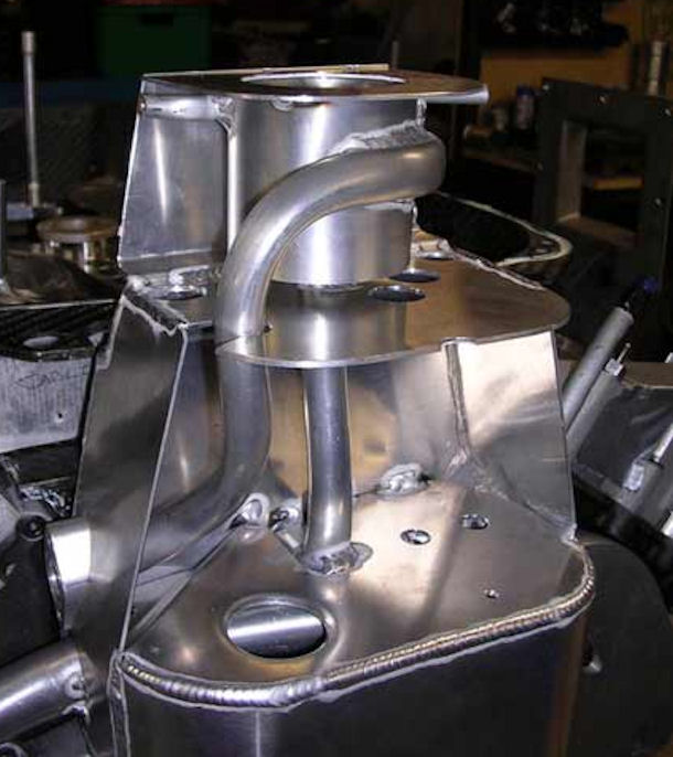
Figure 14: Formula One Oil Tank In Construction (Courtesy of CONCEPT RACING)
POSITIONING of the FILTER and COOLER
One of the most significant errors in oil system implementation is to locate the oil filter and oil cooling heat exchanger in the scavenge pump output circuit. As presented above, scavenge oil is a very low density air-oil froth. As such, the effectiveness of the oil heat exchanger is severely impaired because (a) air is an effective insulator, (b) the aerated froth does not develop the necessary laminar boundary layer flow conditions in the heat exchanger tubes that contribute to the heat transfer effecttiveness, and (c) because of the aerated dilution of the oil, the time each oil molecule gets to spend on a cooler surface is greatly reduced.
The full-flow oil filter will also be compromised by having to deal with the aerated froth in the scavenge return path.
The best layout (as shown in the dry sump schematic diagram, Figure 10 above) is to plumb the output of the pressure pump to the inlet of the filter, the outlet of the filter to the inlet of the heat exchanger, and the outlet of the heat exchanger to the engine lubrication inlet port.
Placing the filter before the heat exchanger has the added benefit of preventing (UNREMOVABLE) contamination into he heat exchanger in case of an engine failure. And no matter what solvent you use, no matter what ultrasound cleaning magic you try, there will still remain some pathological bit of engine debris that will (again, Murphy's Law) find its way into the bearings of the rebuilt / new engine.
