- Mark-27 Gearbox -
A 1.474 Co-axial Propeller Reduction for a VW Engine
NOTE: All our Products, Designs, and Services are SUSTAINABLE, ORGANIC, GLUTEN-FREE, CONTAIN NO GMO's, and will not upset anyone's precious FEELINGS or delicate SENSIBILITIES
There are several other pages on this site that describe various gearboxes we have designed and / or manufactured. Those other pages describe the features of each project. With this page (Mark-27 Gearbox), I will attempt to describe, in some detail, the design process for a Propeller Reduction Gearbox.
In early 2021, I was contacted by a builder who was working on a high-speed, lightweight single-place airplane (Sonerai-1) in which he wanted to use a relatively-high-output VW engine. He inquired whether I would be willing to design a lightweight, short-length, co-axial gearbox for his application, complete with our torsional isolation system, and within definite cost and weight limits.
We traded information for a few days, and after some preliminary analysis, I agreed to give the project a try, knowing out front that the 2nd order torsional excitation produced by an even-fire 4-cylinder engine at a relatively-low RPM (4000) is rather difficult to attenuate.
It should be mentioned here that there two important reasons that the engine torsional excitation should be decoupled from the driven load, in this case, a propeller driven by a gearbox.
The first is to remove the engine torque spikes from being applied to the transmission elements - gears, chains, shafts, fasteners, rubber bands, whatever.
In the case of gears, the gear design can be made considerably lighter and less likely to fail in fatigue if the applied torque is a flat - or nearly flat - line, instead of a pulsing torque value that can be as much as 350% of the mean torque value.
Also, with a relatively soft connection between the engine and gearbox, the dynamic gear tooth loadings can be significantly reduced.
Secondly, it is probably more important to decouple the engine excitation from the propeller. Propeller manufacturers spend a great deal of energy testing and revising their piston engine propellers, especially those in direct-drive applications, to determine if there are engine excitations present that are near a blade natural frequency or harmonic thereof, and making design revisions if such a proximity is discovered.
Losing a piece of a propeller blade in flight can ruin your whole day.
(And adding rubber-bits into the propshaft has virtually no effect on that first goal, and might even AGGRAVATE the second isolation goal.)
PROJECT DETAILS
Here is a picture of the almost-complete powerplant - the VW Engine-with-Mark-27 PSRU.
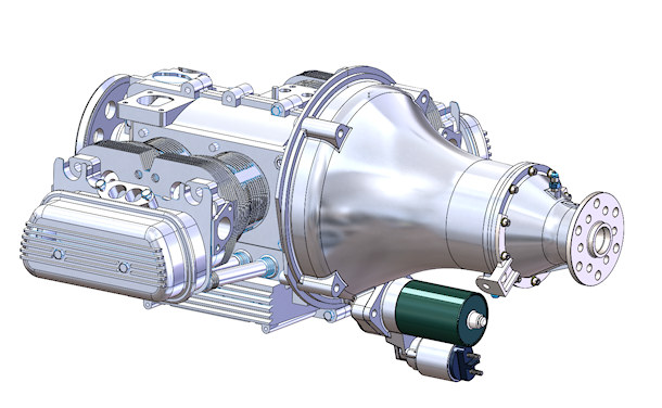
Almost-Complete VW Powerplant with M-27 Gearbox
ENGINE INVESTIGATION
The first set of design data required was a characterization of the proposed engine. The client had selected a 2276 cc (138.8 CI) aftermarket engine based on the VW-1600 design, having a bore and stroke of 94mm x 82mm. If the engine has an appropriate cam, a good induction system, ports with good flow characteristics, good combustion chambers, and an appropriate compression ratio, this engine can reasonably be expected to deliver a peak BMEP of about 175 psi, or a torque ratio of about 1.15. That would put the peak torque at around 160 lb-ft.
In order to do a good torsional attenuation system, we need to make the effective engine MMOI ("J") high and the torsional spring rate of the connection between the engine and input gear of the gearbox quite low.
Initial resonant frequency calculations revealed that, with the MMOI of the propeller the client had selected and a guesstimated propshaft stiffness, that I could get close to reasonable isolation results with a total engine J in excess of 1.0 in-lb-sec² and an input system torsional rate of less than 25 lb-ft per degree.
I calculated the engine J to be 0.364 in-lb-sec², obviously too low. In order to obtain a suitable engine J without adding excessive weight, I acquired an OEM-style 8-dowel flywheel (pictured below), and then proceeded to modify it by removing weight at low radius locations and adding an inertia ring out at the max radius that would clear the starter gear. That modified flywheel is shown in the second picture below.
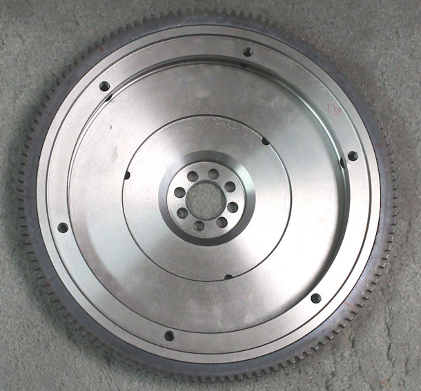
OEM 8-Dowel Flywheel - 14.02 lbs
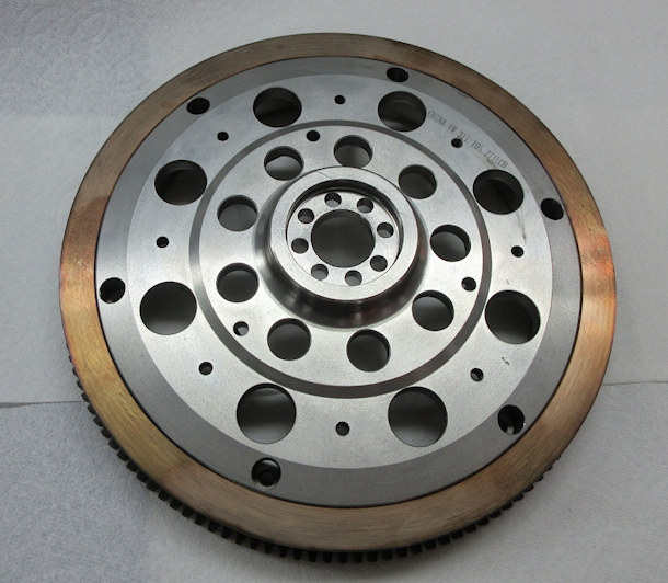
EPI Modified 8-Dowel Flywheel - 16.4 lbs
That modification increased the flywheel MMOI by 36.2% but increased the weight by only 17%.
DRIVE SYSTEM INVESTIGATION
Next, I did some preliminary designs of an input shaft to see how low a torsional rate I could obtain that provided suitable torsional stress levels with an applied torque of 160 lb-ft, and that had a critical speed sufficiently above the max planned operating speed of 4200 RPM.
That study revealed that I could not achieve the required rate with a single shaft alone and stay within the targeted cost and size envelopes. So I surveyed various clutch discs to see if I could find one that was:
- sufficiently robust,
- had a suitably-low torsional rate, and
- had springs that would not be approaching solid height at the planned max torque (160 lb-ft).
I did find such a disc, and by virtue of combining such a clutch-hub with a torsionally-soft input shaft (such as evaluated in the preliminary calculations) I was able (because of the splendid characteristics of springs in series) to achieve under 15 lb-ft per degree.
For anyone interested, the equivalent rate (Ke) of springs ( K1, K2, K3,.....) in series is:
Ke = 1 / ((1/K1) + (1/K2) + (1/K3) + ....)
Next, I analyzed the internal spline in the clutch disc and the mating external spline on the input shaft for the torsional stress under the root, the shear stress at the tooth pitch line and the compressive stress on the tooth flanks, under the loads imposed by 160 lb-ft of torque.
The torsional stress on the input shaft external splines at 160 lb-ft was high enough that my super-strong 300-M alloy steel, heat-treatment, and post processing was required to assure reliability. The pitch line shear stress was 18.3 ksi, and the compressive stress negligible.
The internal spline on the clutch hub has stress levels that are not a concern: relatively low torsional at the root, and the same pitch line shear and hertz stress as the mating external spline.
The completed flywheel-drive assembly is shown below.
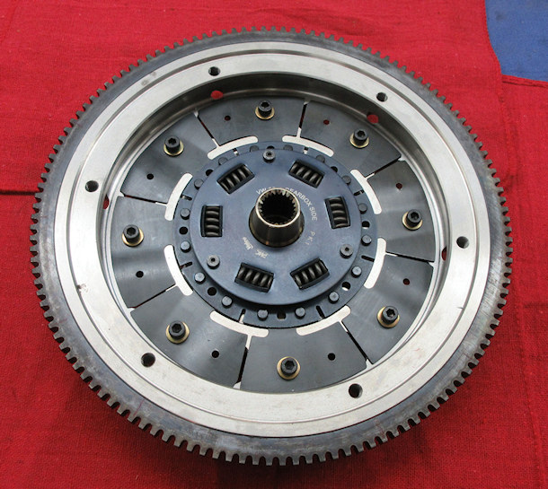
EPI Modified 8-Dowel Flywheel with Spring Drive
GEARSET INVESTIGATIONS
For the reduction hardware, I studied various samples of potentially-suitable automotive planetary gearsets, and found a very nice 6-planet gearset that looked suitable. By using this gearset in the Ring-Driving / Sun Fixed configuration, I could get a ratio that was perfect for this application (1.474).
I purchased a sample of this gearset and disassembled it so I could analyze it in detail. I cut out one of the 6 planet gears / shafts to determine the size and number of needle bearings, and then to determine the probable planet bearing life in this application. Using our life analysis program for full-complement loose needles, the predicted planet bearing life turned out to be over 2000 hours in a typical aircraft load model, based on a max input torque of 160 lb-ft.
I analyzed the gears themselves for static and dynamic loads and stresses. At a steady 160 lb-ft input, the tooth root bending stress safety factor is about 3.5 and the tooth wear safety factor for a 2500 hour life is about 2.0.
PLUS, as an additional feature, the gearset weighs less than 5 lbs.
Lastly, I analyzed the internal spline in the planet carrier (which would become the propshaft output spline) and the external spline on the propshaft that would be driven by this carrier. At a torque load of 236 lb-ft (160 x 1.474), the external output splines are close to my limit for the chosen propshaft material, but the amount of time spent at that loading will be a small fraction of the component's life.
The following picture shows an exploded view of the gearset, as modified to fit this application. To drive the ring gear, I modified the ring gear hub by drilling and tapping six mounting holes (middle item, top row below). In order to keep the cost down, I used the internal spline section cut from another example of the same clutch disc I used for the torsional drive spring (the leftmost item, top row below), and added six mounting holes to mate with the threaded holes in the ring gear hub. I also made a spacer that adapted the spline hub to the face of the ring gear hub, and bolted the spline hub and spacer to the ring gear hub.
I cut the center section out of the drum used to drive the sun gear in in the OEM transmission, added six bolt holes to it (center item, bottom row below) and used that component ("grounding plate") to fix the sun gear to the housing, so as to create the Ring-Driving / Sun-Fixed configuration.
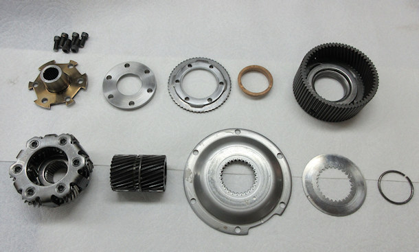
Six-Planet Gearset with Input Spline and Sun-Gear Fixing Hardware
This picture shows the assembled gearset.
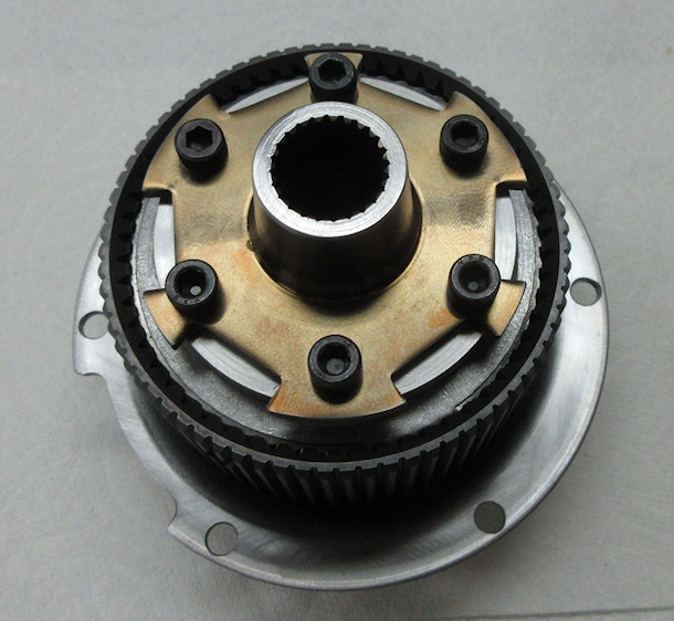
Assembled Six-Planet Gearset Shown in the Preceding Picture
COMPLETE GEARBOX
Having settled on the preliminaries, I began design of the gearbox in detail, using the components described above. The picture below shows the completed gearbox.
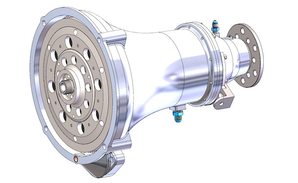
M-27 Gearbox
The following picture shows a perspective-angle cutaway of the complete gearbox.
If you click on this picture, you can load a larger version of it for more detail. To return to this page, use your browser BACK button.
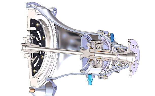
M-27 Gearbox Perspective Cutaway
The main housing is one large 5-axis CNC machining from 6061-T6 billet. The front housing is also a billet-CNC production, and clamped between it and the main housing is a ring to which is attached the grounding plate for the sun gear. The sun gear and the ring gear are mounted in such a way that they can both float radially a small amount, which allows nearly-even load distribution among all six planet gears.
As shown in the cutaway, the input shaft is mostly-hollow, and the aft end pilots in the OEM VW Flywheel Nut / Pilot Bearing. The splines in the spring hub drive the input shaft, which runs in an open cavity between the engine case and the input seal cover. The seal cover isolates the lubricated part of the gearbox by means of a double-lip seal on the input shaft and an O-ring seal junction to the main housing.
The forward end of the input shaft pilots in a close-fitting bearing in the rear of the output shaft, and the forward spline mates with a internal spline that is attached to the ring gear of the gearset. The output spline of the planet carrier mates with an external spline on the output shaft.
There are suitable radial and axial bushings throughout, and the major loads from the output shaft are carried by an SKF-22206-E Spherical Roller bearing that has a very large radial AND thrust capacity.
This bearing calculates out to a projected L-1 life (99% probability of survival) of 3035 hours when evaluated under the following load conditions:
- Max Performance: 10% of the time at 700 lbs thrust and 150 lbs radial (prop) load;
- Max Cruise Performance: 40% of the time at 250 lbs thrust and 150 lbs radial load (75% engine power);
- Cruise Performance: 50% of the time at 220 lbs thrust and 150 lbs radial load (65% engine power).
By comparison, I have seen several gearbox designs in which the propshaft thrust loads are taken by a double-row ball bearing. A double-row ball bearing having the same dimensions as the selected bearing ( 30mm x 62mm x 20mm ) has only 40% of the dynamic load capacity of the selected bearing, and has a fatigue load limit of only 13.7% of the selected bearing.
It should be noted that the determination of a predicted probability of a bearing failure after a certain number of hours is not simply a matter of picking some numbers out of a catalog. Rolling element bearing life is calculated using a set of equations that take into account the combined radial and thrust loadings, and the RPM at several operating conditions that, together, describe the predicted operating environment. The equations also consider the lubrication viscosity and cleanlness, and the desired probability of life.
Details on the determination of rolling element bearing life are discussed in detail HERE.
LUBRICATION
The engine oil pump is a two stage unit that has a high capacity pressure stage and a scavenge stage. The pressure stage supplies filtered, pressurized lube oil to the engine and to the gearbox, and the scavenge stage moves gearbox oil back to the engine sump, after passing through a filter.
Pressurized lube oil enters the gearbox through the AN fitting on the top of the front housing. There are internal passages that directly lubricate the propshaft bearing, and also transfer pressurized oil into the ID of the propshaft. Oil from the ID of the propshaft is pressure-fed to all the bushings and to the gears and planet bearings.
There is a drain passage that allows oil from the bearing to flow back into the main gearbox cavity, which is scavenged by the engine oil pump scavenge stage.
DYNAMICS
The final dynamic analysis of this system is determined from a set of parameters that define the characteristics of a given system.
For an engine-gearbox-propeller system, the analytic parameters are:
- The Effective Engine MMOI (J), including the engine rotating and reciprocating masses, the total flywheel MMOI, and the (reduced) effective MMOI of accessories driven by the free end of the crankshaft (in-lb-sec²);
- The effective MMOI of the idler gear(s) and any rotating shafts and bearing components;
- The Effective MMOI of the propshaft and output gear;
- The Effective Propeller MMOI (in-lb-sec²), typically obtained from the propeller manufacturer (if your manufacturer has no idea about that value, perhaps you might want to consider a different prop manufacturer);
- The Effective Torsional Rate of the gearbox input system (between the end of the crankshaft and the driving gear, including spring elements, elastomer elements, and torsion shaft elements ( lb-ft-per-degree);
- The efective torsional rate of the propshaft between the output gear attach mechanism and the propeller attach flange ( lb-ft/°);
- Gearbox reduction ratio;
- Excitation order to be investigated.
Solving the Holzer Matrix with the values for a particular system produces the system resonant frequency for the excitation order of interest. Subsequent calculations using that solution produce the transmissibilty curve (transmissibility = amplitude ratio - - - output force amplitude / input force amplitude).
The solution for this system is: First mode resonant RPM for a 2.0 excitation order = 541 engine RPM, and the crossover speed is 765 engine RPM.
At an engine idle speed of 1200 RPM, the transmissibility is 0.255. At 3300 ERPM, the transmissibility is 0.028 and at 4000 ERPM it is down to 0.019, providing very effective torsional isolation between the engine and the gearbox / propeller system. The complete response curve is shown below.
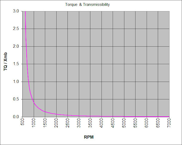
System Torsional Isolation Curve
The client for this project is a skilled engineer AND machinist. The arrangement we had was that he would manufacture the various shafts and housings, and complete the assembly and ground testing. As such, I delivered all the components that I had worked on, the complete set of 3D-CAD models, and the requisite manufacturing drawings and specifications.
The project is currently progressing toward completion. The client has manufactured a sample 3D-Printed housing set to verify the design, and is in the process of machining the input and output system components, as well as the 5-axis CNC manufacture of the various billet housing components.
Here are a few pictures of the project. More will follow when available.
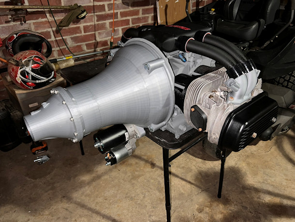
Engine Mockup with M-27 Rapid Prototype Housing Set
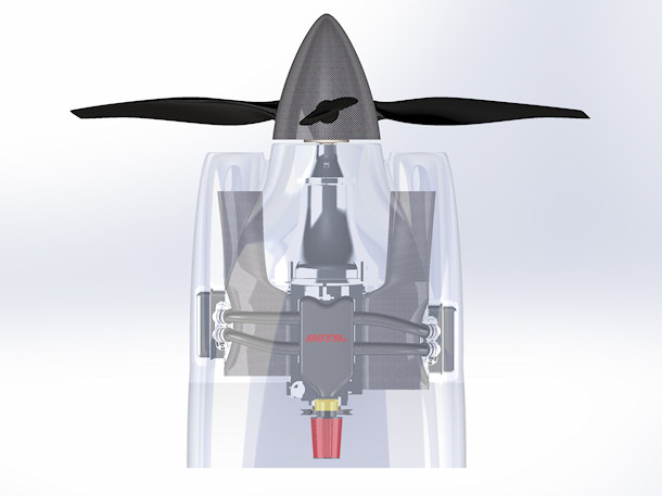
Powerplant Airflow System Design-Top View
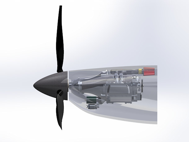
Powerplant Airflow System Design-Side View
