- Rear-Engine, Hemi-Powered Midget Racecar -
State of the Art - For the 1974 Timeframe
NOTE: All our Products, Designs, and Services are SUSTAINABLE, ORGANIC, GLUTEN-FREE, CONTAIN NO GMO's, and will not upset anyone's precious FEELINGS or delicate SENSIBILITIES
INTRODUCTION
This article describes the design, building, and testing of a unique (for its time) oval-track race car, intended to be raced in various "midget race car" organizations. I designed and built this car in 1973 and 1974, and raced it for the first time in the 1974 Thompson Classic, a 100-lap National Championship event on the Thompson high-banked 5/8 mile oval. The first time this car saw competition, it set the 6th fastest qualifying time in this national event.
BACKGROUND
For readers unfamiliar with the term "midget race cars", they consist of a small, lightweight, four-wheel chassis, typically in the 900-1000 pound category, and typically having a wheelbase of 68 to 76 inches, a maximum width of 68 to 70 inches, and a methanol-fueled, limited displacement engine.
(BTW, I have NO IDEA why they are called "midgets". They are a bit smaller than sprint cars, but hardly fit the name "midget". I am 6'5" tall, and many of my competitors were large as well, and fit nicely into these race cars.)
In the 1974 time frame, the engine displacement limit was 155 cubic inches, the size of the small Offenhauser engines commonly used in times past.
Currently (2021) the displacement limits vary from around 140 to 195 cubic inches, depending on the design and features of the engine - - (VW type, inline-4, pushrod, SOHC, DOHC, block material, head material, no hemi-heads allowed, no Wankel engines allowed, etc.). Today's engines are, in most associations, limited to 4-cylinders, and produce in the 300+ HP range.
The typical design contains no conventional clutch, no gearbox, and no starter. Most often, the engine has no flywheel, making it extremely responsive. The engine connects directly to the final drive gear through a short driveshaft.
There is a two position (on, off) lever-operated clutch ("dog-clutch") which connects the engine crankshaft to the short driveshaft. This clutch is disengaged for moving the racecar around the pits and onto the racetrack. When the race is about to begin, the driver engages the clutch and locks up the rear brakes. A push truck gently contacts the rear bumper of the car and starts pushing it (with the rear wheels locked). When the driver senses sufficient vehicle speed for a backfire-free engine start, he releases the brake, causing the rear wheels (and the engine) to turn, and the engine fires off.
The suspension is typically torsion-bar sprung, with a solid, live rear axle having a quick-change center section (Halibrand, Winters, etc) and a solid, kingpin-style front axle.
Back in the 1974 era, there was not much regulation regarding chassis layout. There were traditional "upright" chassis, various side-engine layouts, and my rear-engine layout. The Lindblad "Badger" side-engine design was a favorite, and was very difficult to beat.
Currently, there are several associations that conduct midget races all around the country. Those include USAC with 48 races scheduled in 2021, the Badger Midget Auto Racing Association, and NEMA, the Northeastern Midget Association, in which I raced.
Today, most organizations require an "upright" chassis, that is to say, one in which the driver sits close to the width-wise center of the car and straddles the driveline.
Figure 1 shows a traditional "upright" midget.
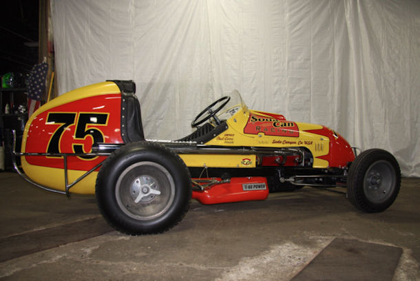
Figure 1: Classical Upright Midget Chassis
Figure 2 shows a contemporary, Toyota-powered upright design.
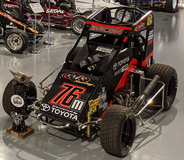
Figure 2: Contemporary Upright Design
Figure 3 shows one of the most famous Lindblad side-engine ("Badger") cars, powered by a very highly-modified Chevy-II inline-four cylinder pushrod engine. This car was owned by legendary NEMA President John McCarthy and won the NEMA championship in 1970, 1971 and 1973.
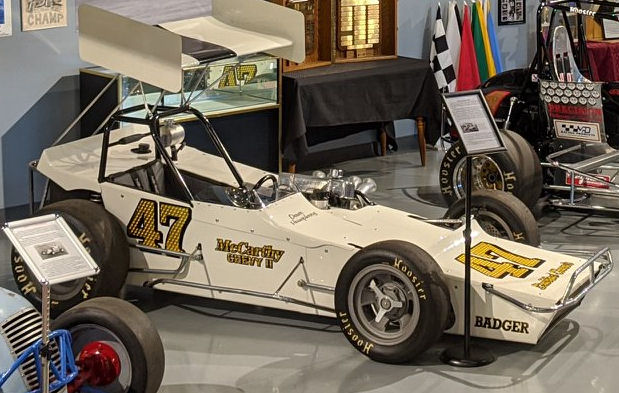
Figure 3: McCarthy-Lindblad Badger Midget
The basic specifications described above provide a very high performance race car that is challenging to drive, and very entertaining to watch. Most often, the races are conducted on various size dirt / clay tracks, with the occasional foray onto a paved track.
Probably the most famous nationally-known midget race is the "Chili Bowl", known as "The Super Bowl of Midget Racing". This is an event that takes place two weeks after Christmas over a span of 6 days in the Tulsa (OK) Expo Raceway, an indoor 1/4-mile flat clay track that seats approximately 15,000 fans, and is essentially sold out for the next year by the end of the current year's event.
The Chili Bowl draws top level drivers from all forms of racing: USAC, WOO, IndyCar, NASCAR, NHRA, and others. The 2021 race drew 317 entrants (HERE is the entry list) including NASCAR stars Chase Elliot, Christopher Bell, Kyle Larson, Ryan Newman, Kasey Kahne, Chase Briscoe, Justin Algaier, Brett Moffitt, and JJ Yeley.
The racing is extremely competitive and intense. EVERY driver wants to win The "Golden Driller" award. NASCAR star Christopher Bell won in 2017, 2018 and 2019; NASCAR star Kyle Larson won in 2020 and 2021. Other notable winners include Sammy Swindell (5 wins), and Tony Stewart (2 wins).
Just to put the capabilities of these cars into perspective, in 1959 the famous road course at Lime Rock Park, CT hosted a well-publicized Formula Libre race, in which there were entered all manner of exotic road race cars - and one upright, USAC midget. This car was driven by the legendary Rodger Ward (WW2 P-38 fighter pilot, 2-time Indy-500 winner). He shocked the expensive and exotic sporty-car crowd by beating them all convincingly, on the road course, in a 155 cubic inch Offenhauser powered midget race car having NO gearbox, NO clutch, and NO starter. Ward used an advantageous power-to-weight ratio and his considerable skill as a race car driver to steal the win.
RACE CAR DEVELOPMENT
In 1971 I was racing a Brabham BT-21 Formula-"B" car (180 MPH top speed, 1.5g cornering capability). During a late-1971 race on the Thompson Speedway Road Course, a suspension component broke in the middle of a 130-MPH corner and sent me over a 10-foot dirt embankment into the trees.
Figure 4 below shows my BT-21 an hour BEFORE the incident.
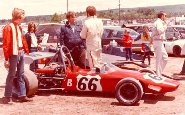
Figure 4: BT-21 Before Last Race
Figure 5 shows the remains of the car in Figure 4, wedged up against a tree, after the heroic corner workers pried the chassis far enough out of the dirt to get me out. Visible in Figure 5 is the cavity that the rollbar punched in the ground as the car came to rest.
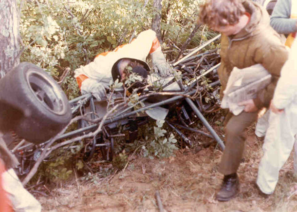
Figure 5: Aftermath of an Airborne Excursion
After that near-fatal experience, I decided that the costs and risks involved did not justify racing for trophies. Racing for MONEY seemed to be a much more prudent path, so I went into oval track racing, drove for two different owners, won a few championships, and then got an opportunity to drive a (one-off) side-engine midget for the owner.
That midget racing experience convinced me that I "needed" one of my own. At that time, the rules were quite open, and I thought I could build a competitive car on the extremely-limited budget I had available (feeding the family always came first).
Based on my road-racing experience in very-fast rear-engine open wheel cars, I decided on a rear-engine layout, with fully-independent suspension controlled by coil-over-Koni double-adjustable (bump and rebound) shocks, with fully adjustable front and rear anti-roll bars, outboard disc brakes, rack-and-pinion steering, and dimensions that fit within the NEMA rules.
Figures 6 and 7 show the finished product on display at the 1974 Boston Auto Show.
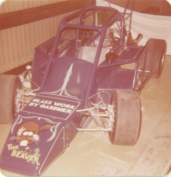
Figure 6: Left Front View -:"The Beaver" on display at The Boston Auto Show
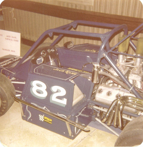
Figure 7: Left Quarter View -:"The Beaver" on display at The Boston Auto Show
CHASSIS DESIGN AND CONSTRUCTION
I began with a design concept and some 3-view pencil drawings. That work evolved into a 1/10-scale chassis model that I built from soldered-together bits of brazing rod. The major chassis design goals were:
- To achieve a chassis torsional stiffness greater than 6000 lb-ft-per-degree so that the suspension could be more easily tuned and more repeatable to drive,
- To achieve the lightest possible frame having acceptable stress levels, and
- To accomplish those goals with a 74-inch wheelbase, truss-frame vehicle.
Once the "stick model" was completed, I used an IBM Truss-Structure design program (available on the large mainframe Univac-1108 system at Pratt & Whitney Research Labs, where I worked in 1973) to analyze the stress levels and stiffness of the design. I had to move a few sticks around to get the stiffness and stress levels I wanted, but in the end, the goals were met.
Next, I produced 2D drawings from which the chassis would be built. I constructed a layout fixture table in my shop, set up supports for the major intersection points, and began to cut tubing and weld.
The chassis was oxy-acetylene welded from mild steel tubing. The main rails of the chassis were 1.25 x 0.049 wall tube; The diagonals were 0.875 x 0.049 wall tube; The bulkheads were 1 x 2 x 0.084 wall rectangular tube, and the roll cage was 1.50 x 0.093 wall tube.
Figure 8 shows the chassis at an advanced stage of completion on the fixture table in my shop.
There are two side bays, one on either side of the driver bay. Those side bays serve two purposes. First, they provide the triangulation needed to restore the torsional stiffness lost because of the open top of the driver bay. Second, they provide room for necessary components - the fuel tank, the oil tank, and the engine pumps..
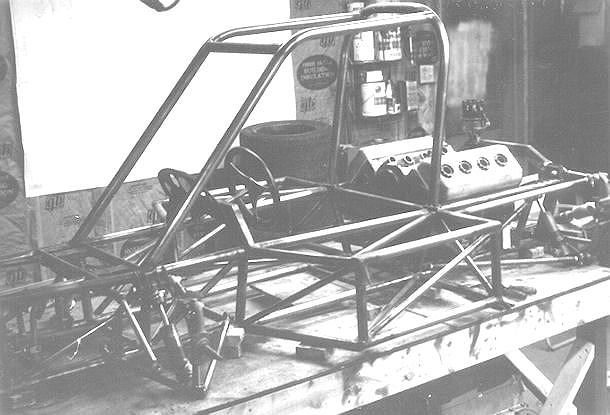
Figure 8: Chassis Construction
The left side bay held the fuel tank, with an Aero-Tec Labs bladder and foam filler. The right bay held the pumping subsystem (oil pumps, fuel pump, and coolant pump, described later) along with the oil filter, custom-fabricated oil tank, and plumbing components.
The left-bay location of the fuel cell was advantageous from a left-side weight bias standpoint when it was full, but as fuel burned off, the car CG moved aft and to the right, negating the side bias, and adding oversteer to the setup.
Figure 8 also shows the suspension components attached to the chassis.The suspension design was the result of many hours of iterative computer work using a FORTRAN program I wrote to analyze suspension parameters. The inputs were X-Y-Z pivot-point locations, suspension component dimensions, and suspension deflection values to be studied. From those data, it calculated, for the specified deflections, roll center location, caster, camber, and toe changes. Using that program, I arrived at a front and rear suspension design that satisfied my goals for roll center locations and travel, and near-zero bump steer.
From those results and my drawings, I fabricated the suspension components from 4130-N tubing, built the welding fixtures to hold the components in place, and had an expert TIG welder I knew put them together.
I had salvaged a few critical suspension components (front and rear uprights, stub axles, half-shafts, disc brakes and hydraulics, etc) from my wrecked BT-21, and those became the basic components of the new suspension design.
Figure 9 shows the finished chassis on wheels. The wheels are 13-inch diameter Minilite Mags, 7 inches wide in the front and 10 inches wide on the rear. The tires were tubeless Firestone racing semi-slicks, 4.25 x 9.50 front and 5.00 x 11.00 rear.
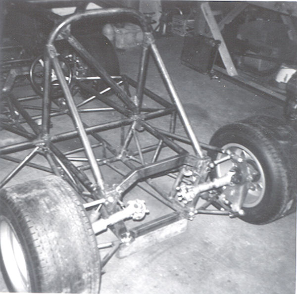
Figure 9: Chassis Completed
POWERPLANT DESIGN AND CONSTRUCTION
As part of the overall vehicle design process, I did some considerable research into what might make a suitable engine. I decided to use a small 2.5 liter hemi V8 from the Daimler SP-250 British sporty-car as the basis for my powerplant.
This engine has an iron block with aluminum hemi heads. The bore and stroke are 2.992 x 2.756, (76 x 70 mm) which comes in just barely at the 155 cubic inch limit. The conrod-to-stroke ratio is 1.85, which helps to reduce the cylinder wall side loading. Further, the iron block has a reasonable longitudinal polar moment of inertia, which when coupled with the additional torsional stiffness added by the heads and the full girdle (covered below) allowed me to use the engine as a semi-stressed component in the chassis, which further increased the overall torsional stiffness of the whole vehicle.
As a matter of convenience and preference, I decided to include a standard clutch and starter motor in my design. That decision was also part of a futile attempt to convince the NEMA management that starters on all the cars would make the overall show more interesting to spectators by eliminating the ever-boring need for multitudes of push-trucks to get an event going.
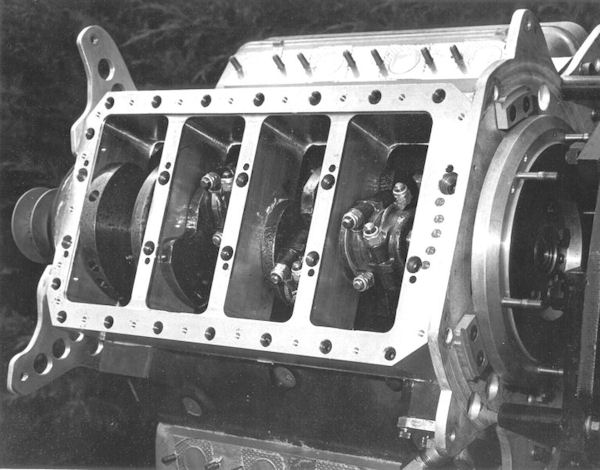
There were some issues to be solved with the basic engine configuration. First, the bottom end of the block, especially the main bearing webs, looked quite fragile. To remedy that problem, I took an idea from Bruce Crower's 1972-1973 208 cubic inch Smallblock Chevy Indy Car engine, and carved a one-piece bottom end girdle from a 3 x 10 x 18 brick of 7075-T6 aluminum.
The owners of the company at which I was then employed were kind enough to allow me to use their machine shop on weekends, and so their Bridgeport, lathe, bandsaw, and surface grinder were reassigned to building race car parts instead of parts for their Computer-Controlled Optical Scanner products.
The girdle attached to the block with high-strength allen-head capscrews, using the original main bearing bolt locations as well as a full perimeter attachment using what had been the sump bolt locations. When the girdle was finished to the point that the main bearing bores were roughed and it could be fully bolted and doweled to the block, I took it to my favorite auto machine shop and had the block-and-saddle assembly precision align-bored.
Figure 10 shows the block with the saddle and rear motor plate attached.
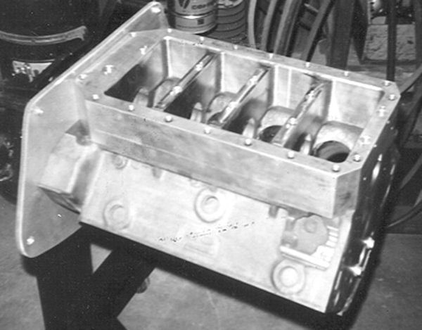
Figure 10: Block with Saddle and Rear Motor Plate
While I was whittling large bricks of aluminum, I made a deck plate to enable the finish hone of the cylinders under the same stress / deflections as would occur when the heads were attached and torqued to spec.
Figure 11 shows the deck plate attached to the left bank of the block, with a head attached to the right bank to assure a close match to the stresses the block experiences when fully assembled, to achieve optimal cylinder roundness during honing.
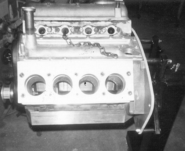
Figure 11 Block with Deck Plate and Head Attached
The Daimler SP-250 crankshaft is a decent piece. It is a two-plane steel forging (made from EN-40B, I was told) with good a counterweight layout, although it lacks center-main counterweights (not a huge issue for a crank with such a short stroke). It has cross-drilled rod and main journals, with drilled galleries connecting the main and rod journals - - not the optimal setup for high RPM oiling, but probably deemed adequate when the engine was designed. The rod journals are drilled on the center axes, reducing the counterbalance requirements. I had the crankshaft journals ground 0.010 under with fully-radiused 0.125" fillets, shotpeened in the journal fillets, 55% overbalanced, and used it in that form.
The OEM conrods looked adequate, so I polished the beams, had them shotpeened, then remanufactured the small and big ends, and equalized the center-to-center distances. I installed high strength allen-head capscrews and aircraft self-locking nuts, and used the OEM wristpins, retained with double-Tru-Arc rings, back-to-back.
Forgedtrue made the custom-designed domed pistons for me. They raised the compression ratio from the stock 8.2 to the final 14.5 (coupled with an 0.030 slice off each head). I used stock Daimler intake valves and custom-made, high-temperature Donovan exhaust valves. I used the valve springs and retainers from the DOHC Lotus-Ford inline-four, and modified a set of Smallblock Chevy pushrods to fit the engine.
The OEM Daimler shaft-mount rocker arms were about the only practical choice, but I stiffened the rocker assembly by installing tightly-fitting spacers made from 0.250-wall tubing onto the OEM rocker shafts between the rockers, which significantly stiffens the shaft and rocker assembly.
The camshaft provided an interesting challenge. The OEM camshaft was a steel production that used steel cam followers with radiused Stellite tips that were furnace brazed onto the lower ends of the followers. The cam followers ran in bores (perpendicular to the cam axis) in the valley cover, and were anti-rotated by virtue of a flat surface on the side of the radiused follower end that mated with a parallel surface on the aluminun valley cover.
The stellite tips were worn on my engine, and I did not like the potential reliability issues presented by the brazed-on tips. So I discarded the OEM cam followers, cut away the alignment surfaces on the valley cover, and manufactured a set of suitable flat-tappet cam followers by grinding the OD of the big ends on a set of '57 Ford 312-V8 Chilled Iron mushroom tappets to a diameter that would clear the adjacent cam lobes. I then machined the lifter bores in the valley cover to the correct diameter for these new mushroom lifters.
I sent the steel camshaft off to Crane Cams and asked for a grind suitable for the application and for the flat tappet configuration. They provided me with what turned out to be an excellent grind. I don't remember the basic cam specs ( that was 1973 - just a few years before this 2022 writing ). The OEM Daimler double-row roller-chain cam drive with the hydraulic tensioner was adequate for the application.
Figure 12 shows the engine near final assembly.
 .
.
Figure 12: Engine Nearing Final Assembly
The dry-sump oil system consisted of a 3-stage Aviaid pump (one pressure stage, two scavenge stages), the remote oil filter, a custom-made dry sump oil pan, and a custom-made oil tank with de-aeration features inside. The Aviaid oil pump also had the Hilborn methanol-compatible fuel pump attached to the end of the pressure stage.
The oil pump, fuel pump, and the coolant pump comprised the Pump Module, located in the right side bay of the chassis. The Pump Module was driven off the nose of the crank by a custom-designed two-stage Gilmer Belt system. The coolant pump came from a marine system, and provided more than enough pressure to supply the coolant flow rate required for the engine at full power.
Figures 13 and 14 show the engine Pump Module.
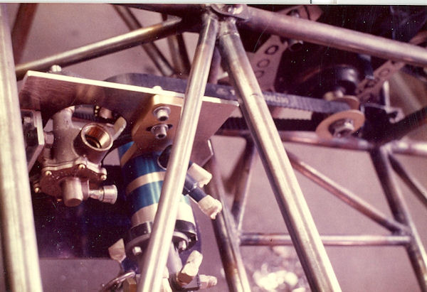
Figure 13: Pump Module, Top View
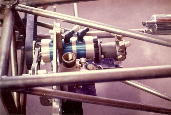
Figure 14: Pump Module, Side View
The intake and fuel system for this engine was an innovative piece of work. There was no aftermarket fuel injection system available for a Daimler SP-250 engine. So I designed a system with equal-length tubular runners feeding from a 2x volume plenum.
The throttling function was achieved by one half of a Hilborn V8 fuel injection 4-port throttle body, cut in half and turned 90°.
The standard Hilborn fuel metering system provided the correct fuel delivery to the eight constant-flow injector nozzles, one positioned in each manifold runner.
Figure 15 shows this intake system.
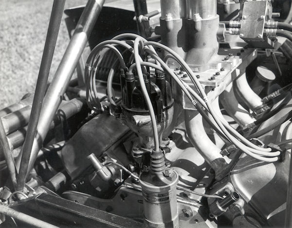
Figure 15: Intake, Fuel Injection, and Ignition Systems
Also shown in Figure 15 is the ignition system, consisting of an OEM Daimler distributor with a tailored centrifugal advance curve, modified with a transistorized Judson ignition trigger and a "Flamethrower" coil.
The exhaust system consisted of a pair of headers having equal-length 1.375" ID x 28" primaries converging into 2" x 12" collectors.
The cooling system was based on a pair of 3-inch thick aluminum Harrison air conditioner heat exchangers located in matching air tunnels above each of the outer frame bays, tipped forward at a 45 degree angle (visible in Figure 5). The coolant pump in the pump module drew coolant from the 4-corner coolant outlets in the heads and delivered it to the heat exchangers. From there, it flowed back to the engine coolant inlets. There is an overflow / equalizing tank connected to the inlet side of the pump, which contains the pressure-regulating cap and sufficient expansion volume.
POWER TRANSMISSION SYSTEM
As mentioned in the general description above, the typical midget / sprint car / champ car layout does not use a transmission gearbox. The speed ratio between the engine crankshaft rpm and the wheel rpm is established by the combination of a 90 degree, spiral-bevel gearset having a 4.125 ratio, combined with a set of spur ("quick-change") gears that have ratios ranging from 0.48 to 2.1. Those components are compactly housed in the rear end center section, and can provide overall ratios ranging from 1.98 to 8.66. The quick-change gears are exactly that - they can be changed out (in matching pairs) for a different ratio-set in less than 15 minutes.
For the transmission system of my rear-engine midget, I used a Halibrand live-axle center section, with modified side plates and a spool modified to accommodate sliding splines for my half-shafts. To couple the drive system to the engine, and to accommodate the starter motor and 3-disc racing clutch that I included in the design, I cut the bellhousing section off a Porsche transmission, welded a flat plate to the back side of it, and machined that plate to bolt directly to the front of the Halibrand center section.
Figure 16 shows the bellhousing in progress, before I welded the aluminum plate to it. The starter attach flange is also visible in this picture.
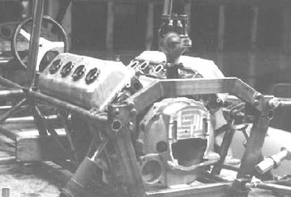
Figure 16: Bellhousing in Progress
The triple-disc clutch (also salvaged from the BT-21) mounts to a custom flywheel that is shown in Figure 14 (before the starter ring gear had been installed).
Figure 17 shows a top view of the nearly-finished final drive mechanism. In that picture, the halfshaft drive stubs are shown having conventional cross-joint universals. Later in the construction process, I replaced those with VW constant velocity joints. Looking back, that was a bad design decision, the product of ignorance, mixing CV joints with non-CV cross joints.
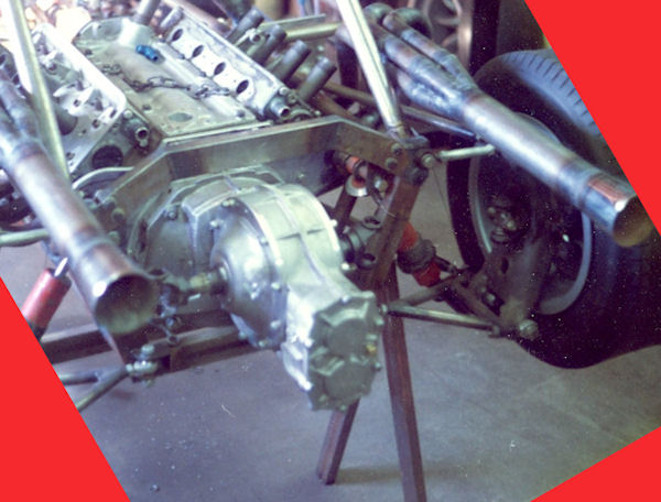
Figure 17: Final Drive Nearing Completion
Figures 18 and 19 below show the completed, ready-to-be-painted racecar (nicknamed "The Beaver", for what reason I cannot imagine).
The engine started on the very first try, and appeared to run very well. That success motivated some full-throttle acceleration runs through the neighborhood streets. That test was very gratifying, and I got the car back into my shop just moments before the Gestapo arrived on scene.
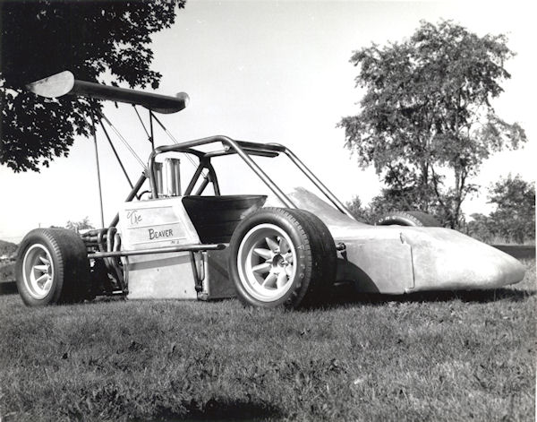
Figure 18: Right Front View of Completed Midget
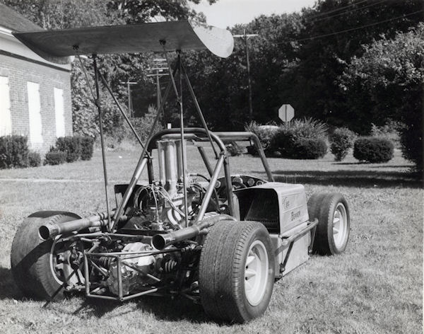
Figure 19: Right Rear View of Completed Midget
FIRST RACE
The first race in which I ran "The Beaver" was the 1974 Thompson Classic at the Thompson, Connecticut high-banked 5/8 mile oval. Figure 20 shows my pit crew rolling the car out onto the starting grid.
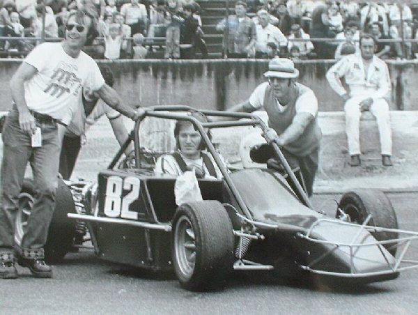
Figure 20: Pit Crew (Jim Jordan, Skip Jones {hidden}, and Crawford Kus) Rolling The Car To The Grid
Nearly 50 top level cars from all over the eastern half of the country attempted to qualify for one of the 33 starting spots. I was able to qualify "The Beaver" with the 6th fastest time of the meet, which was the first time the car had been run in competition.
Figure 21 shows Chris Economaki (ABC Wide World of Sports) interviewing the owner / builder / driver just before the start of the race. Although I built the car with a wing (shown in Figures 18 and 19), the NEMA rules did not allow wings at that time.
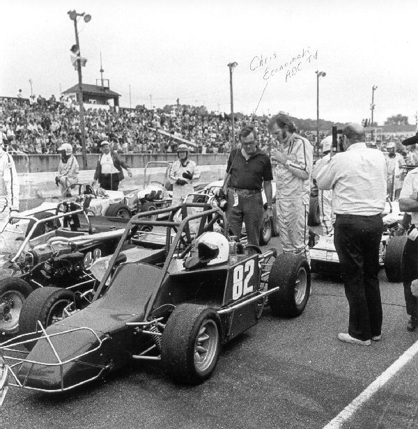
Figure 21: Chris Economaki Interviewing Builder / Driver
Figure 21 shows the start of the race, 11 rows, 3-wide, in which the top 12 qualifying cars had their starting order inverted (fast time started 12th, 12th-fastest time started on the pole).
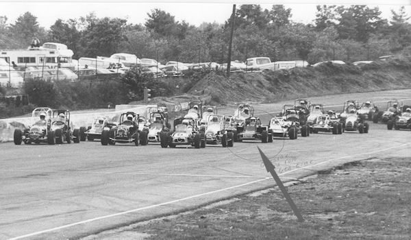
Figure 22: 11 Rows, 3-Wide "Indy-Style" Start
Figure 22 shows the new rear engine midget making an outside pass into third place, around one of the leading Badgers.
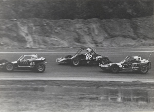
Figure 23: Outside Pass Into Third Place
Although the car ran very well in the Thompson Classic, regrettably a fuel-injection linkage bolt loosened and fell out, causing me to retire from the race just before halfway.
The next race was at Seekonk Speedway in Massachusetts, a fast 1/3 mile, slightly-banked asphalt track. During qualifying, I spun on track. As is the common practice in rear engine cars during a spin, I just locked up the brakes and depressed the clutch pedal, keeping the car off the wall, and keeping the engine running.
HOWEVER, as is the common practice at midget and sprint car races, my spin caused an immediate yellow flag and the dispatch of a push-truck. But when my car came to rest, I simply re-engaged the clutch and drove off. The announcer went hysterical, having never seen such a thing before.
The March-1975 issue of Hot Rod Magazine carried a detailed article, written by Terry Cook, about the design, construction, and racing of this unique racecar.
In late 1975, I moved to California for a new job, and, of course, took the racecar with me. There was no time during 1975 to play with it at all.
In early 1976, I took it to the Bakersfield Speedway for some testing. At that time, Bakersfield was flat 1/4 mile paved oval. (In 1992 it was converted to a 1/3 mile banked clay track.) During that testing session, I was well-below the existing track record lap time. Unfortunately, I had not set the car up quite right for a short, flat track, and after quite a few laps, encountered a terminal understeer condition, probably because I was trying to go ever faster. That resulted in a brutal encounter with the third turn wall, which wiped out the right front suspension and bent the frame.
It languished, broken, on its trailer in my driveway for a year. I finally sold it to an ambitious builder in Southern California, and have no further information on its fate.
