Installation Notes for the EPI Secondary
Transmission Upgrade for RotorWay Helicopters
Information Critical to the Safe Installation of Your New Secondary
NOTE: All our Products, Designs, and Services are SUSTAINABLE, ORGANIC, GLUTEN-FREE, CONTAIN NO GMO's, and will not upset anyone's precious FEELINGS or delicate SENSIBILITIES
Document Number 240005
REVISION HISTORY
| ID | Date | Description |
|---|---|---|
| A | 09/10/04 | Initial Release. |
| B | 02/05/05 | Complete revision: added installation recommendations on lower bearing, tailrotor pulley, fan hub, cone locks. |
| C | 03/22/05 | Added specification for light machine oil; fixed error in Fan Hub installation instructions re: retaining ring orientation; replaced reference to Loctite 641 with 609; revised to describe new lube system (hsg -F mods); revised most sections for better clarity and more detail; added new sections. |
| D | 04/14/05 | Expanded the section describing the tightening sequence for the cone lock. |
| E | 11/22/05 | Changed picture and text in Sections 5 and 8 to reflect new configuration of Upper Bearing Housing (-G mods); Revised and reordered Sections 22 thru 25 to include instructions for the EPI High-Capacity cone lock as well as the older low-capacity part. |
| F | 12/15/05 | Added note about bearing temperature range. |
| G | 05/09/06 | Added Sections 2, 3 and 4 to GENERAL INFORMATION and renumbered subsequent sections. |
| H | 03/03/07 | Added drive preload reminder (Section 16) after one user installed the upgrade without setting the preload on the tooth belt, and broke a belt. |
| J | 04/04/07 | Clarified Loctite instructions (Sections 22, 23, 24); Clarified friction lock torqueing instructions (Section 25); Fixed s everal typos. |
| K | 12/09/07 | Expanded and clarified Section 27. |
PLEASE READ THESE NOTES CAREFULLY BEFORE ATTEMPTING
TO INSTALL YOUR UPGRADED SECONDARY SYSTEM
1. This document covers several important topics related to the successful installation of your upgraded secondary assembly: (a) general information, (b) upper bearing details, (c) lower bearing details, (d) installation of the tail rotor drive pulley; (e) installation of the fan hub (f) installing the cone-friction lock which attaches the main rotor drive sprocket to the secondary shaft.
GENERAL INFORMATION
2. When you turn the shaft in the EPI upper bearing by hand, it may seem to be tighter than the original RotorWay installation. That apparent tightness occurs for several reasons:
- The EPI seals are brand-new and have a snug fit to the shaft;
- The new seals have substantial surface area and there is very little grease in the seal contact area until the system has been operated;
- The new seals are substantially larger in diameter (28% on the lower, 9% on the upper) than the old ones, so even with equivalent seal-friction drag, they exert more drag torque on the shaft than the original equipment;
- Although the bearing has C3 internal clearances, the combination of the interference fit on the shaft and in the housing causes the internal clearance inside the bearing to decrease, giving the appearance of tightness at room temperature; (We measure the internal clearance of each bearing after it has been installed on the shaft to verify that it is sufficient.)
- The bearing has been filled with an excessive amount of grease (explained in detail in Section 9) which adds drag.
3. We strongly recommend that your instrument panel be equipped with a gauge which displays the temperature of the upper bearing housing. That temperature can be measured by means of a ring-type temperature sensor secured to the upper bearing housing by the zerk fitting.
4. Our customers report that during the initial two-to-four hours of operation, the temperature of the upper bearing housing can get as high as 180°F, especially in a hover. However, after the bearing settles in and the quantity of grease in the bearing has reached equilibrium (see Section 9), then the operating temperature of the bearing should stabilize at approximately 60°F above the ambient temperature. After shutdown the upper bearing temperature will spike approximately 25°F because of the heat built up during operation and the stoppage of cooling airflow.
5. The new EPI secondary shaft in your upgraded secondary assembly is made from an extremely high quality steel, which has been processed to achieve a very high strength. When handling the assembly, take special care not to scratch or otherwise damage the surfaces of the new shaft.
6. EPI has applied a light coating of corrosion inhibitor to the exposed shaft surfaces between the autorotation clutch assembly and the upper bearing assembly. Note that the remainder of shaft has no corrosion protection applied to the surface because that would interfere with the proper installation of the cone friction lock and the setting of the Loctite anaerobic products used on the lower bearing, tailrotor pulley and fan hub bearing.
After your secondary is completely installed, you can extend the protection of the secondary shaft by applying an aircraft-style corrosion inhibitor such as LPS-3 to all the exposed areas of the shaft, both above and below the main drive pulley. If you do apply a protectant, be careful that none of it gets onto the sheave surfaces of any of the V-belt pulleys.
7. EPI recommends that your aircraft not be left exposed in a damp or condensing environment because unprotected steel corrodes quickly, and, as with any steel, any corrosion will reduce the life expectancy of the shaft material.
UPPER BEARING INFORMATION
8. The EPI upper bearing assembly (shown in Figure 1) eliminates the RotorWay feature which allows the lower seal to be blown out of the bearing housing during regreasing or during operation. Our system (a) retains the seals with a shoulder and a large retaining ring, and (b) provides a pressure bleed which prevents pressure from building up behind the seals, either from the injection of new lubricant or from the increase in temperature which occurs when the bearing is in operation.
Figure 1 shows the important external features of the EPI Upper Bearing Housing. The grease (zerk) fitting is located on the lower-rear corner of the housing. When grease is pumped into this fitting, internal passages inside the housing direct grease into the lower face of the bearing. The grease moves upward in the bearing, covering all the moving elements, and escapes out the bleed port in the opposite upper-rear corner of the housing. This bleed port allows fresh grease to be pumped completely through the bearing, while preventing the lower seal from being damaged or blown out.
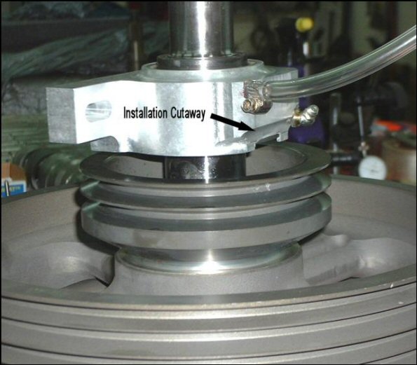
Figure 1
There is a clear neoprene tube attached to the bleed port. (We sincerely thank Orv Neising for the idea of the clear tube.) This tube serves several purposes: (a) it prevents grease, which normally escapes after a regreasing operation, from contaminating the drive belts, (b) it allows the operator to monitor the amount of grease which bleeds off after the injection of fresh grease into the bearing, and (c) it prevents contamination from entering the bearing due to cooling-contraction.
The installation cutaway (shown in Figure 1) is a machined relief in the lower rear face of the housing, to allow this larger-than-standard bearing housing to slip into the airframe easily. This feature is discussed further in Section 15.
Slightly port of center on the lower part of the mounting face, there is a small, recessed allen-head setscrew which prevents the lower seal housing from rotating. It is installed with a substantial dab of Loctite, and should never move. Do not mess with this setscrew. If you think there is any problem with it, contact EPI.
UPPER BEARING GREASE
9. Because of the fact that RotorWay has declined to reveal just how much grease they put into a new bearing in production, we decided to overfill the bearing with grease, under the theory that too much is way better than too little. The upper bearing has been filled with Citgo Mystic JT-6 High Temperature grease.
During In the first few hours of operation after you install your upgraded secondary, the upper bearing will expel the excess grease and will stabilize at the proper operating level. After the bearing stops expelling this excess grease, it would be wise to remove the clear tube, clean it out, and re-install it. By cleaning it out, the rate of subsequent grease loss can be more closely monitored.
Continue to grease the upper bearing in accordance with the instructions provided by the aircraft kit manufacturer or in accordance with the procedure you have developed for your aircraft.
Anytime you add grease to the upper bearing, it is possible that a small quantity might escape from the bottom face of the housing in the area of the installation cutaway. When you are adding grease to the upper bearing, it is wise to put a paper towel or a rag under the rear portion of the upper bearing housing to catch any grease which escapes. When you are finished, be sure to wipe up any grease which has escaped from the housing or the zerk.
One further note on the bleed tube: Because the grease which escapes from the bearing is hot and likely more like a liquid than a solid, it might be a good idea to install the bleed tube in the airframe in such a way that it curves upward a bit before pointing downward toward your catch-can or overboard drain. That will allow you to more accurately monitor the amount of escaped grease.
10. EPI has machined the mounting face of the upper bearing housing to match the angle measured from the one on the assembly you provided for upgrade (or, to the angle which you specifically requested). When the housing is installed on the bearing, it is VERY DIFFICULT to accurately machine this face and to avoid introducing contamination into the bearing. If, for some reason, you need to change this angle, we recommend you consider returning the assembly to EPI for this modification.
11. EPI has NOT installed any temperature-sensing buttons on the upper bearing housing. However, EPI strongly recommends that you provide one or more means to monitor the temperature of the upper bearing assembly, either by applying the temperature buttons used by the factory, or by the installation of a real-time temperature instrument which reads out in the cockpit (or both).
INSTALLATION OF THE SECONDARY ASSEMBLY IN THE AIRFRAME
PLEASE READ THIS SECTION CAREFULLY
12. When EPI disassembles the secondary system which you sent us for upgrade, we attempt to establish the exact vertical location of your lower secondary bearing. If we are able to establish that vertical location, then we re-install your new lower bearing in the exact same vertical location it was in on the old assembly. In that case, we did a complete installation of your lower secondary bearing, tailrotor pulley and fan hub bearing. They are installed, Loctited in place, eccentric collar tightened, setscrews torqued, and the system should be ready for installation into your airframe.
Because we replaced your lower bearing, the sheet metal pillow block clamping screws are loose so you can get the correct alignment of the pillow block on your airframe. Don’t forget to tighten them.
HOWEVER, if for some reason we were not able to determine the correct vertical location of the lower bearing (if, for example, you sent us a secondary which has not yet been installed in your ship), THEN your upgraded secondary system was shipped with the lower bearing, tailrotor pulley and fan hub bearing components installed loosely in place. As a part of your installation, you will have to do the additional steps of aligning the lower bearing to your satisfaction, and then doing the Loctite-collar-setscrew operations on the lower bearing, tailrotor pulley and fan hub bearing yourself. Sections 19 through 24 in the following instructions provide some guidance on how to do this process successfully. Your RotorWay construction manuals provide additional guidance.
13. Most of the builders who have installed our Secondary Upgrade report that it is not necessary to remove the lower bearing, tailrotor pulley and fan hub from the secondary shaft assembly before installing it into the airframe compartment where it lives.
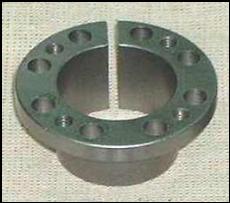
Figure 2
14. Removing the Drive Sprocket. The 8 bolts in the friction lock holding the main rotor drive sprocket bolts are snugged, but not torqued. Note the presence of four threaded holes between the bolts in the friction lock flange (shown in Figure 2). Those 4 holes are the push-off holes and are used to unlock the mechanism. (If this is unclear, see the pictures on Page 15.)
Remove four bolts adjacent to the push-off threads and install them into the push-off threads until they lightly contact the lower cone. Back off the remaining 4 bolts about 3 turns. Using a 5 mm hex wrench, tighten each of the 4 push-off bolts about ¼ turn, in sequence, until the inner cone releases. You can then remove the drive sprocket from the shaft.
15. The EPI Upper Bearing Housing must be carefully positioned relative to the airframe tubes in order to install it into the airframe bay where it lives. (Note: the factory 35mm system is similarly snug, and in some cases, it is very difficult to install.)
The machined relief in the lower rear portion (the INSTALLATION CUTAWAY shown in Figure 1 and shown in Figure 3 below from a different angle) allows it to move closer to the round tube at the rear of the secondary bay, behind the square tube where the upper bearing mounts.
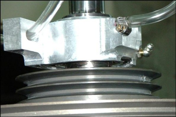
Figure 3
NOTE: You must remove the zerk fitting in order to get the bearing housing to go into place. If access to the zerk is a problem, a 12-point box-end wrench with a thin wall makes removal and installation much easier. You can make it from a standard wrench by thinning the wall with a grinder or sander. It will probably help if you also remove the clear bleed tube from the screwed-in adapter.
Figure 4 shows the position of the upper bearing housing during installation. The correct orientation of the Upper Bearing Housing will result in just enough clearance at the bottom front edge of the 8-sheave drive pulley to allow it to pass by the lower square tube where the lower bearing mounts in the airframe, as shown in Figure 5.
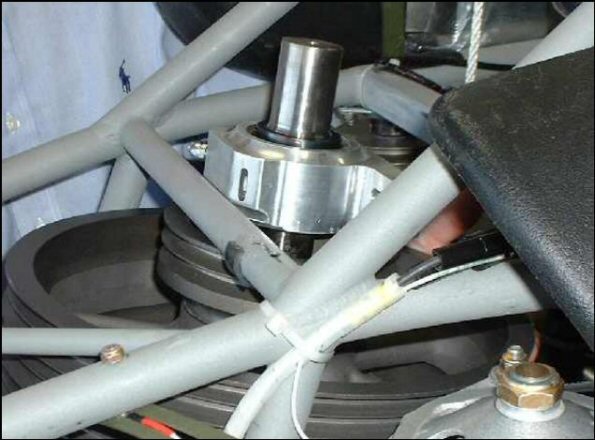
Figure 4
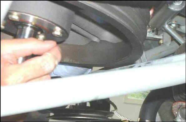
Figure 5
16. As part of the installation procedure, it will be necessary for you to (a) realign the secondary shaft and upper bearing housing according to the instructions provided by the factory or in accordance with your preferred procedure, (b) set the main rotor drive chain or belt preload recommended by the drive manufacturer, and (c) set the tailrotor belt preload recommended by RotorWay.
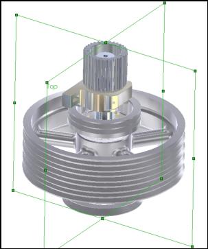
Figure 6
PLEASE TAKE CARE to align the secondary shaft with your main rotor shaft in both the fore-aft plane and the port-starboard plane, as shown in this picture.
Next, the upper face of the upper bearing housing must be perpendicular, IN BOTH PLANES, to the aligned secondary shaft.
Although the upper bearing can operate successfully with as much as 1.5° of total misalignment, EPI recommends that you try to achieve the lowest possible misalignment, and ideally, no more than ½° in both planes in order to assure optimum functioning of the bearing and seals.
LOWER BEARING DETAILS
17. NOTE: AS EXPLAINED IN SECTION 12 (above) YOUR LOWER BEARING, TAILROTOR PULLEY AND FAN HUB COMPONENTS MIGHT NOT ALREADY BE BONDED TO THE SECONDARY SHAFT.
In many cases, EPI can determine the correct vertical location of the lower bearing for YOUR AIRCRAFT and replicate that location on your upgraded assembly.
IF the secondary which you sent to EPI for upgrade was one which had been removed from your aircraft, EPI measured the location of the lower bearing on the old secondary shaft, and reinstalled it in the same vertical location on the new shaft.
In that case, the lower bearing inner race has been bonded onto the secondary shaft with Loctite-609, the eccentric lock has been tightened, and the setscrew which holds the eccentric in place has been tightened.
We tightened the eccentric collar opposite the direction of shaft rotation. (We are aware of the controversy about the proper tightening direction. We have no opinion on that subject; the direction we use is just simpler.) We encourage you to verify that the eccentric and setscrew are tightened to your satisfaction.
Because we replaced your lower bearing, the bolts which clamp the split pillow block together are loose so that the pillow block can be aligned with the airframe. Be sure to tighten those clamp bolts after the shaft has been installed and aligned.
If EPI has installed and bonded your components (as described in Section 17 above), you may skip directly to Section 25.
IF EPI WAS NOT ABLE TO FINAL-INSTALL THE LOWER BEARING
18. IN CERTAIN CASES, EPI will not be able to determine the correct vertical location of the lower bearing for your aircraft (if, for example, you sent us a secondary assembly for upgrade which has not previously been installed on your aircraft).
If that was the case, then we did not tighten the lower bearing collar eccentric or the setscrew, the tailrotor pulley, the fan hub bearing, and no Loctite was applied to any of those components. You will have to determined the correct vertical location of the lower bearing on the shaft, and then install those components as described in Sections 19 through 24.
19. In order to complete this procedure correctly, you will need to get some acetone and a 10-ml bottle of a product known as Loctite-609 (Loctite P/N 60921). Get the Loctite-609 from a bearing store such as Applied Industrial Technology, Kaman Industrial Technologies, Motion Industries, MSC Industrial Supply, etc. You can get a can of acetone at stores such as Home Depot, Lowe’s, and maybe Mom and Pop’s Hardware.
CAUTION:
DO NOT LET SOME COUNTERJOCKEY AT A CAR PARTS STORE CONVINCE YOU THAT "....EVEN THOUGH HE DOESN’T HAVE LOCTITE-609, THE STUFF HE DOES HAVE IS JUST THE SAME".
IT MOST PROBABLY IS NOT THE SAME.
There are nearly a hundred different Loctite adhesives, many of which are RED, many of which are GREEN. Each has a different product number, because each performs differently (different strength, different temperature limits, different cure times, etc.)
20. Removing the fan hub. The vertical position of the fan hub on the secondary shaft is determined by a retaining ring in a groove at the very bottom of the secondary shaft.
Using a sufficiently-long 1/8 hex wrench, be sure the two setscrews (just below the lower edge of the tailrotor pulley) are loose.
Using a quality snap ring tool of the appropriate size, carefully remove the retaining ring and mark it with a magic marker to indicate which side of the retaining ring was facing downward.
Remove the hub from the shaft. Put the hub in a clean plastic bag until you are ready to install it, and keep your fingers off the inner race of the bearing. ( WHY? Because your fingers are probably not clean, and grease, oil, even body-oils, can interfere with the complete curing of the Loctite).
21. Remove the tailrotor pulley and set it aside where it will not get dirty, oily or damaged. Keep your fingers off the ID of the pulley (Same reason). You do not need to record the position of the pulley on the shaft, because the process which EPI uses to drill the bolt hole is so precise that the bolt will slide through in either of the two angular orientations.
22. After you have bolted the upper bearing housing in place, slide the lower bearing vertically on the shaft to align it with the bolt holes in the airframe.
The bolts which clamp the split pillow block together are loose so that the pillow block can be aligned with the airframe. Be sure to tighten those clamp bolts after the shaft has been installed and aligned.
After you have determined the correct vertical location for the lower bearing and tightened the two pillow-block clamp screws, make a locating shim which fits between the lower bearing and the bottom of the clutch so that you can move the lower bearing and easily replace it in its correct vertical location.
Wet a clean paper towel with acetone and use it to clean the entire surface of the shaft below the lower bearing.
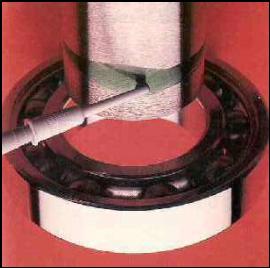
Figure 7
Unbolt the lower bearing pillow block from the airframe and slide the lower bearing downward on the shaft. Clean the area of the shaft where the lower bearing was with a clean paper towel wet with acetone.
Apply a small, even amount of Loctite-609 to the OD of the shaft in the area just below where the bearing will end up (NOT at the bottom of the shaft as in Figure 7).
Slide the lower bearing back into place against the locating shim you made. Bolt the pillow block in place to hold the bearing in its location until the Loctite sets (at least 30 minutes)
After the Loctite has set, finish tightening the lower bearing eccentric collar as usual and tighten the setscrew which holds the collar in place. Consult your factory instructions for the recommended tightness.
TAILROTOR DRIVE PULLEY INSTALLATION
23. When you are ready to install your tailrotor pulley, wet a clean paper towel with acetone and clean the OD of the entire secondary shaft below the lower bearing, and the ID of the pulley. Apply a thin ring of Loctite-609 to the area of the shaft just below where the tailrotor pulley resides, and slide the tailrotor pulley into place, rotating it as it moves upward, to distribute the Loctite evenly inside the bore. Install the AN-4 bolt, washers and nut per factory instructions. Be quick about it in order to get the pulley aligned before the Loctite sets. DO NOT TIGHTEN THIS BOLT until about 30 minutes after installing it. That allows the Loctite to harden evenly around the ID of the pulley, helping to prevent fretting of the shaft.
FAN HUB INSTALLATION
24. When you are ready to install the fan hub, wet a clean paper towel with acetone and clean the OD of the entire secondary shaft below the tailrotor pulley, and the ID of the fan hub bearing.
Apply a thin ring of Loctite-609 to the area of the shaft just above the retaining ring groove and slide the fan hub onto the shaft, pushing it upward as far as it will go. Quickly install the retaining ring into the groove on the secondary shaft, and pull the hub downward so that it is securely located against the retaining ring. Be sure the down-facing side of the retaining ring that you previously marked in Section 20 is facing down when you install it here.
Wait for the Loctite to set (approximately 30 minutes) before tightening the two setscrews on the hub bearing inner race. That allows the Loctite to harden evenly around the ID of the pulley, helping to prevent fretting of the shaft.
FRICTION CONE-LOCK INSTALLATION
25. All the current main rotor drive devices (chain sprocket, ProDrive toothbelt sprocket and Behuncik toothbelt sprocket) are fastened to the upper journal of the secondary shaft by means of a conical friction locking device. The correct installation of this device is critical to your safety and that of your passengers.
The following sections describe the installation of the (optional) EPI high-capacity cone lock. If you are using the low-capacity cone-lock, the smaller torque values to use are shown in parenthesized (green) text.
Figure 8 shows both the EPI high-capacity friction lock (left) and the more common low-capacity product (right).
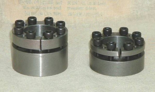
Figure 8
FIRST, in order to install this device correctly, IT IS ESSENTIAL THAT YOU USE A GOOD QUALITY TORQUE WRENCH, reading in INCH-POUNDS, of no greater than about 240 inch-pounds capacity.
NOTE: You are attempting to tighten 8 critical bolts to 150 (120) inch-pounds of torque. That is only 13 (10) foot-pounds. YOU WILL NEVER GET IT RIGHT using a 100 foot-pound wrench.
In order to illustrate this point, the next two pictures show the remains of a cone-lock which a meticulous builder carefully installed with a good 100-foot-pound wrench.
While attempting to get to the correct torque, he snapped one of the 8 bolts, and when he removed the remaining 7 bolts, he found that (a) all the remaining 7 bolts were bent under the heads, (b) the surface of the lock flange was gouged under the heads of all the bolts, and (c) he had severely deformed the bolt flange of the upper lock piece.
Study the next two pictures. Note how the flange is bent downward; note the depth of the gouges the bolt heads put into the flange; note how the gouges are much deeper near the ID of the flange. Then decide whether you want to be careless with this step.
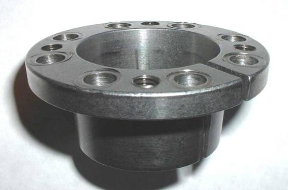
Figure 9
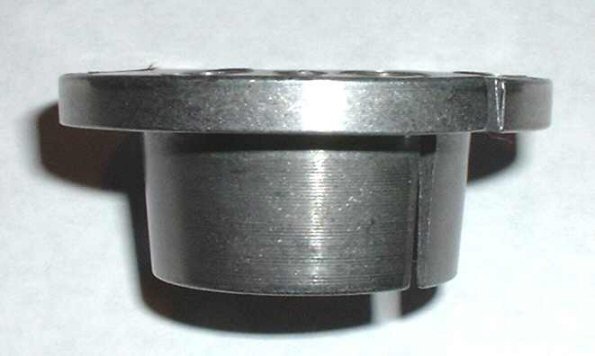
Figure 10
OK. Now, if you don’t already have one, call your Snap-On guy and get yourself a good inch-pound torque wrench with a range of no greater than 240 inch pounds. You’re supposed to be an aircraft mechanic, so you should have proper tools.
26. When installing the friction cone lock (described in the next section) it is important that you perform the tightening of the bolts in a cross-pattern (described next paragraph) which minimizes the effect which tightening a given bolt has on the other 7 bolts.
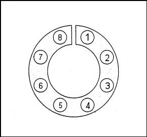
Figure 11
The following text describes the sequencing method we use. It is not easily shown in a picture, so you will have to visualize the pattern from this description.
Figure 11 shows each bolt with a number corresponding to its position.
The tightening pattern we use is a criss-cross pattern which indexes clockwise. Here is the sequence for the first two rounds of tightening:
1,5,2,6,3,7,4,8,5,1,6,2,7,3,8,4
After two rounds, the pattern repeats itself. Visualize the sequence on the picture and it will be clear.
We have found that this sequencing method of provides the least amount of iterating to attain the recommended torque. HOWEVER, BE PREPARED FOR THE FACT THAT THIS STEP WILL REQUIRE MANY, MANY TIGHTENING ITERATIONS.
27. The following is the cone-lock installation procedure, extracted from the instructions published by two different manufacturers of friction cone-lock devices.
REMEMBER: If you are using the low-capacity cone-lock, the torque values to use are shown in parenthesized (green) text.
The friction lock assemblies are supplied lightly oiled and ready for installation. They are self-centering and fit straight-thru hub bores. Note that the friction lock assembly permits axial movement during installation.
The torque-transmitting capacity of these friction lock devices is based on a coefficient of friction of 0.12, appropriate for lightly oiled screw, cone, shaft and bore contact areas.
Therefore it is very important NOT TO USE any oil with high pressure additives, any grease, or any Molybdenum Disulfide product (e.g. Molykote, Never-Seez or similar products) anywhere in this friction lock.
- Make sure the contact areas of the locking screws, cone, shaft and bore are clean and lightly oiled. Use a light machine oil such as CRC-Industrial 3-36 Multipurpose Lubricant and Corrosion Inhibitor (No motor oil: It has additives).
- Make sure the slits in the inner and outer sleeves are oriented 180° away from each other (as delivered). (One manufacturer suggests installing the locks with the slits aligned. EPI prefers the 180° separation.)
- Loosen the locking screws 3 to 4 turns and transfer 2 or 3 screws to the push-off holes. Finger-tighten those screws to be sure the cones are separated during assembly.
- If you have removed the friction lock assembly from the sprocket bore, replace it in the bore and install the sprocket and lock onto the shaft.
- Remove the locking screws from the push-off holes and replace them in their locking-screw locations.
- Set the desired vertical location of the sprocket with shims. Be aware that when you tighten the locking screws, the sprocket will move upward on the shaft slightly.
- Using an allen wrench or t-handle wrench, snug the locking screws according to the tightening pattern shown in Section 26. Tighten the screws in small increments until they do not turn easily and the cone-lock has become fixed to the shaft and the ID of the sprocket.
- Set your torque wrench to 75 in-lb. Using the tightening pattern shown in Section 26, tighten each locking screw ¼ turn. Continue this process until ¼ turn can no longer be achieved without exceeding the wrench setting.
- Set your torque wrench to 155 (125) in-lb. (slightly above the specified torque of 150 (120) in-lb.).
- Make 2 more complete passes at the 155 (125) in-lb setting. This over-torqueing is required to compensate for the fact that tightening a given screw will always relax adjacent screws. Without over-torqueing, an infinite number of passes would be required to reach a specified torque.
- Now, reset your torque wrench to 150 (120) in-lb and check each locking screw in sequence. None of the screws should turn.
28. For the sake of completeness, we provide the following copy of the RotorWay friction cone-lock installation instructions. Note how the sequence shown below does not provide the same incremental tightening action as does the one described in Section 26. ALSO, please note that the following instructions were published with reference to the low-capacity friction lock.
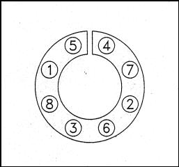 |
"Diagram 13: The screws must be tightened gradually and in several stages, using the tightening sequence shown. The bolts must be torqued to 10 ft-lbs. Note: As described above, the locking assembly and sprocket mayhave a tendency to rise while the bolts are being tightened. Height must be verified after the bolts are tightened." |
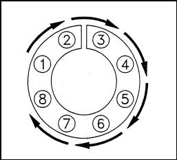 |
Diagram 14: After installation is complete, check (the) torque of the screws again in a clockwise or counterclockwise sequence. Make sure that none of the bolts can be turned at 10 ft. lbs. (120 in. lbs.) Note: After the first hour of operation, re-check the torque of these bolts. If any looseness is detected, recheck the torque at subsequent intervals until the bolts remain tight. |
NOTICE:
Your safety and the safety of your passenger and others on the ground depends on the correct operation of your autorotation clutch.
Please take special care to TEST the correct operation of your autorotation clutch before EVERY takeoff. You should be able to observe a rapid split of the rotor RPM and engine RPM needles anytime the main rotor speed is up, by quickly rolling off the throttle.
If there is any question in your mind about the proper operation of the autorotation clutch, discontinue the flight as soon as safely possible and attempt to determine the cause of the anomaly.
