- EPI Gen-1 Aircraft V8 -
Performance, Parts, Development
NOTE: All our Products, Designs and Services are SUSTAINABLE, ORGANIC, GLUTEN-FREE, CONTAIN NO GMO's, and will not upset anyone's precious FEELINGS or delicate SENSIBILITIES.
NOTE: THIS PROJECT IS NEARLY 30 YEARS OLD. WE ARE NO LONGER PRODUCING ANYTHING BASED ON THE OLD SMALLBLOCK CHEVY BECAUSE WE ARE CONVINCED THAT THE NEWER, LS-BASED ENGINES ARE SUPERIOR IN SEVERAL IMPORTANT WAYS. I AM LEAVING THIS PAGE ON THE SITE FOR ENGINE-BUILDING TIPS and INFORMATIONAL PURPOSES ONLY.
The Gen-1 Aircraft Engine Program began in 1993, and the first version of the engine was completed in 1996. It was a lightweight, normally-aspirated liquid-cooled V8 with specially-developed top-end and bottom-end components, designed for (a) maximum reliability and (b) excellent performance. It had completely-redundant ignition systems with two spark plugs per cylinder and a specially-developed mechanical fuel injection system.
The Gen-1 engine engine was a reliable, liquid-cooled, normally-aspirated aircraft powerplant which produced 500 HP for takeoff (4500 RPM) and 455 HP at max cruise (4000 RPM). It weighed 512 pounds, complete with dual ignition, Bendix-style mechanical fuel injection, fuel pump, dual alternators, vacuum pump, PSRU torsional absorber system and the bulletproof Mark-9 PSRU, with prop governor.
Driven by cost considerations as well as the engineering need for a better cylinder head design, this powerplant was discontinued in early 2001 and replaced by our Gen-2 engine program.
Although this page describes the First Generation EPI aircraft V8 in it's finished form, the actual development process was incremental, with each step forward being based on research and testing of various options and configurations.
The Gen-1 engine has been successfully tested for many hours at 4500 RPM (500 HP, max takeoff power) and at 4000 RPM (455 HP, max cruise power). The BSFC is 0.465 at takeoff power and 0.435 at max cruise (91% power). The performance curves are shown in the graph below.
FIGURE 1: Power, Torque, and BSFC of Gen-1 Aircraft Engine
The following pictures show some of the components used in the Gen-1 engine.
Here is a nearly-complete Gen-1 engine, shown without the proprietary-technology intake system and exhaust headers, which are key components in the superior performance of this engine.
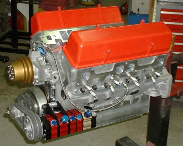
FIGURE 2: Gen-1 Engine (without Intake, Exhaust, and Ignition Systems)
An excellent engine must begin with an excellent cylinder block. This block is a GM product, made from high-grade A-356 alloy, heat-treated to the T6 condition. All 5 main bearings have 4-bolt bearing caps made from heat-treated 8620 steel. The block is completely CNC-machined, and is exceptionally accurate when we receive it.
Even with such an excellent block, it is necessary to compensate for the imperfections of production machining. We remove all burrs and flashing, and chase all tapped threads. Next is an elaborate cylinder-wall finishing process to assure perfectly-round cylinders, exceptional ring-sealing, and low wear. We then add oil jets which cool the underside of the pistons and meticulously clean all oil passages. Finally, the entire block is cleaned by a special process which ensures the removal of all remaining bits of hone abrasive left embedded in the cylinder walls.
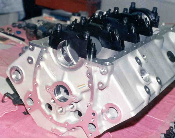
FIGURE 3: High-Grade Aluminum Block from GM
The next major component is the crankshaft. In order to assure we get the material and processing we specify, we purchase raw forgings, inspect them to verify they are non-twist forgings, inspect them for visual flaws, magnaflux them, and test a sample of the material to verify it is the E-4340 vacuum-arc-remelt we ordered.
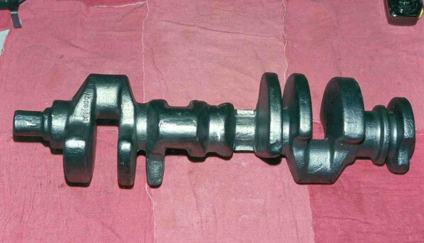
FIGURE 4: Raw Non-Twist AQ-4340 Crankshaft Forging from GM
After the forgings pass the incoming inspections, they are sent to one of the country's premier crankshaft manufacturers to be machined to our specifications, providing our engines with the best quality crankshaft available.
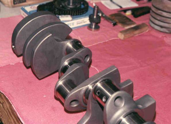
FIGURE 5: Finished 4.00 Inch Stroke Crankshaft
Likewise, our connecting rods are optimized for the load conditions they will bear. They begin as high-quality forgings of E-4340-AQ steel. The profile is machined to provide block and camshaft clearance with the stroke we use, the external surfaces are treated for high fatigue resistance, and the rods are fitted with the strongest stud-fasteners available.
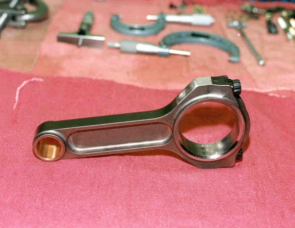
FIGURE 6: 4340 I-Beam Conrods
The pistons are very-high-quality parts, optimized for heat tolerance, strength and wear characteristics. They are forged from slices of 2618 extrusions. The tops are finished to assure an optimal combustion chamber configuration, identical on all cylinders. H-11 tool-steel wrist pins are fitted to precise alignment and clearances, and retained with dual spirolox retaining rings.
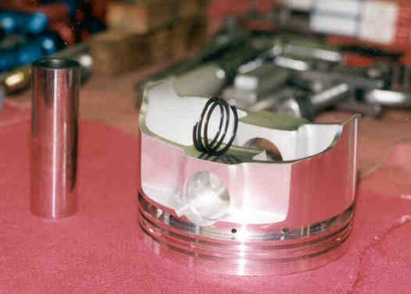
FIGURE 7: 2618 Forged Piston, with Wristpin and Retainer
After many preparatory operations, measurements, trial assemblies and more measurements to verify and assure correct dimensions and clearances, the bottom end is meticulously assembled. Because of the necessity to get precise preload values in the conrod fasteners, we do not rely on torque. Instead, a dial-indicator tool is set up to measure the stretch in the rod bolts and the main bearing cap studs. The nuts are tightened to achieve a specific stretch value, thereby assuring correct and consistent clamping load.
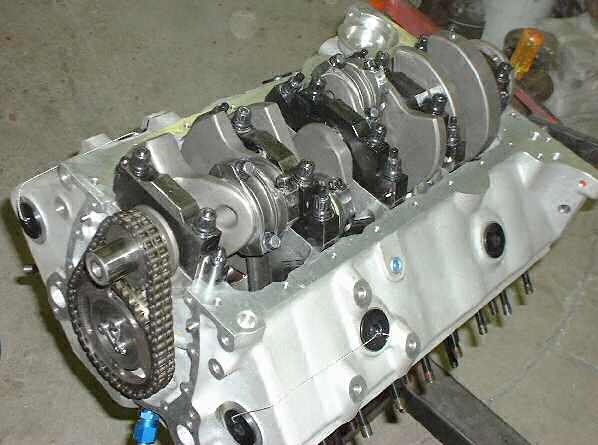
FIGURE 8: Completed Bottom End
Because of the original target application for the Phase-1 engine (unlimited aerobatic competition), it used a dry-sump lubrication system, based on a Barnes pump, an EPI-designed dry-sump pan, and an EPI oil tank which assured uninterrupted oil supply in any orientation.
The Barnes Pump has an iron pressure-section housing to keep clearances small at operating temperature, with ball bearings on the driving shaft at critical locations. The driven gears in all five sections are aluminum-bronze. The pump was fitted with an EPI redundant HTD toothbelt drive, that includes a fence to separate one belt from the other. In the case of a belt failure, that fence prevents the failed belt from dislodging the other one. Each belt has sufficient capacity to drive the pump alone in case one fails.
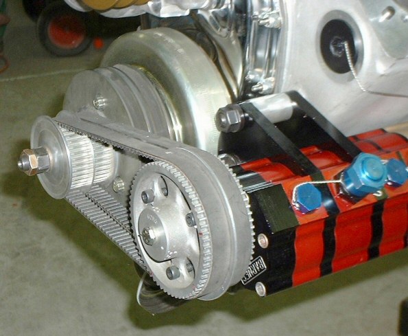
FIGURE 9: Dry Sump Oil Pump and Drive
The dry sump pan was developed for optimal separation and channeling, and was manufafctured by STEFS. Our later engines use a very sophisticated wet sump system which reduces the windage loss to the same level as the dry-sump, but cuts about 30 pounds off the installed engine weight and reduces the cost.
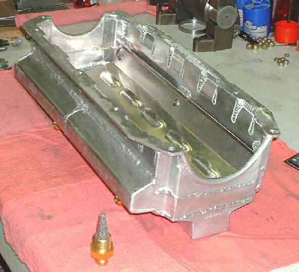
FIGURE 10: Gen-1 Dry Sump Pan
Well-developed cylinder heads are an essential part of any high-performance engine. Due to the limited availability of custom castings at the time, our Phase 1 dual-plug cylinder heads were based on an existing casting from AllPro.
That casting used the sub-optimal standard SBC layout, in which each combustion chamber is a mirror-image of its neighbor. That puts the two center-cylinder exhaust ports adjacent to each other, which can cause excessive temperatures and premature material softening in the bridge between those center cylinders. The side-by-side intake ports make the implementation of optimal intake manifolding a challenge. Each combustion chamber has two spark plugs, although neither plug is located in an optimal position.
We installed valve seats with optimized configurations and, for that ancient timeframe, optimized materials. We conducted an extensive development program on our computer-data-acquisition flowbench, during which the port, valve, seat, and chamber configurations were refined.
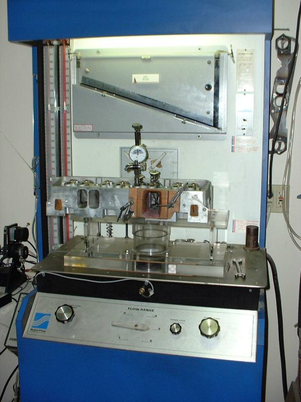
FIGURE 11: Dual-Plug Head on Flowbench for Development
When the configuration was optimized, we developed a CNC program for the combustion chambers and all the ports. CNC machining assures that all cylinders are identical in flow and burn characteristics.
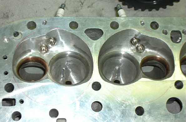
FIGURE 12: Finshed Combustion Chambers, Ports, and Spark Plug Coolant Passages
Extensive modifications are necessary to provide adequate head cooling, including the drilling of coolant holes to remove heat from around the spark plug bosses (shown above) and drilling coolant passages to force coolant through the bridge between the center cylinders (shown below), lowering the bridge temperature by a measured 150°F.
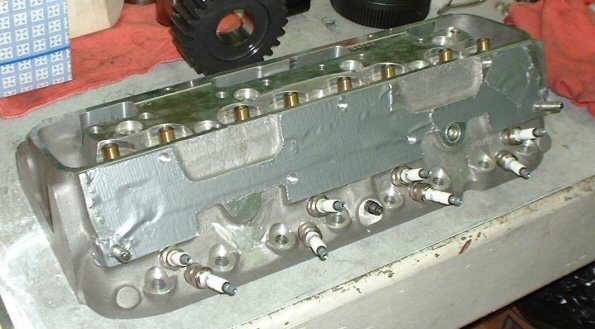
FIGURE 13: View of Head showing Center Bridge Coolant Passage
Our cylinder head castings are machined to nearly-finished form on the 5-axis CNC machining center at the shop of a highly successful NASCAR engine builder for whom we do R&D work.
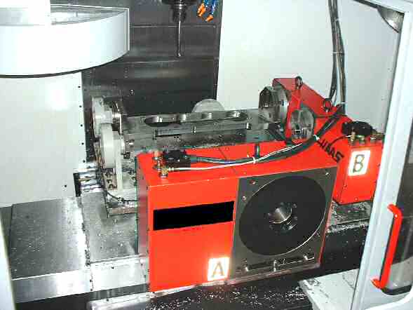
FIGURE 14: Five-Axis Head Machining Setup
In addition to excellent cylinder heads, a well-optimized valvetrain is essential to both high output and long life. Using our computerized cam lobe measuring system from AUDIE TECHNOLOGY, we were able to develop cam lobe profiles to work with the cylinder head flow characteristics and provide the tailored torque curve needed to achieve the desired performance.
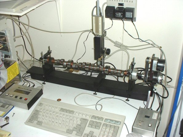
FIGURE 15: Gen-1 Camshaft on EPI's Computerized Cam Measurement System
The valves, lifters, pushrods, spring retainers and rocker arms were optimized for stiffness, strength and reliability. The dual valve springs were specially developed for optimal reliability. We determined the resonant frequency for both springs needed to avoid the higher amplitude harmonics contained in the cam lobes and to provide a suitable separation from each other. The result was an exceptionally stable and reliable valvetrain.
Valve-spring cooling is a significant issue in a long-life engine. If you put a valve spring on a table in a 70°F room and operated it in the same way it is operated in an engine at 4000 RPM, the temperature of that spring will rise dramatically, due to internal friction (hysteresis). In the hot environment of an engine, the problem gets worse. We use specially-developed rocker covers which incorporate an oil-spray nozzle for each valve spring, to assure proper spring cooling.
This picture shows the steel shaft-rocker configuration. A common mistake some builders make is to use aluminum rocker arms, probably OK for race cars, but not good for 2000 hours of life.
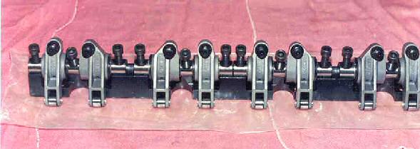
FIGURE 16: Crower Steel Rocker System for SBC
In order to optimize cooling, we use a coolant pump which can move 100 gallons-per-minute through the engine while consuming only 5 HP. This pump has a redundant drive (visible in the top picture of the assembled engine), so the loss of one of the belts will not cause circulation failure.
The coolant flow has been optimized to provide even temperature distributions across the engine. Part of that optimization includes the use of what is known as "4-corner-flow", in which coolant is removed from the front and back of both heads and flows to our bypass thermostat adapter.
In order to provide fast warmup without hotspots or local boiling, our thermostat system circulates coolant back to the pump until operating temperature is achieved. At that point, coolant is routed to the heat exchanger and the system maintains coolant temperature throughout the operating range.
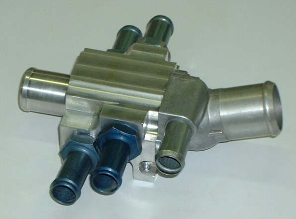
FIGURE 17: Thermostat Housing for 4-Corner Coolant System
In order to eliminate the need for separate external air passages for an oil cooler, we use an oil-to-water heat exchanger to cool the oil. This aids in a fast warmup and the maintenance of optimal oil temperatures under all flight conditions.
Although our Gen-1, Phase-2 engines have a purpose-designed, fully integrated accessory drive, our earlier versions used a toothbelt-driven vacuum pump, mounted to our ball-bearing drive unit and driven off the coolant pump pulley.
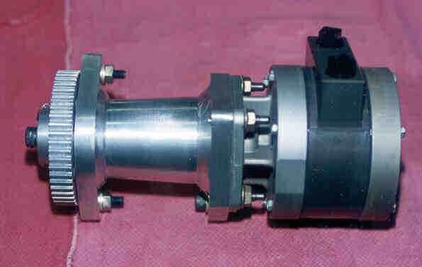
FIGURE 18: Toothbelt-Driven Vacuum Pump
Our redundant ignition system was based on two modified HEI-type distributors, driven by a geared adapter which EPI designed and manufactures. That adapter moves the two distributors out of the way of the special long-runner, X-ram intake system. We chose the HEI style because of its proven insensitivity to static discharge, its very low current draw (in case of electrical problems requiring battery operation in flight) and its very high output in the speed range of this engine. This system is shown below, with one of the distributors removed.
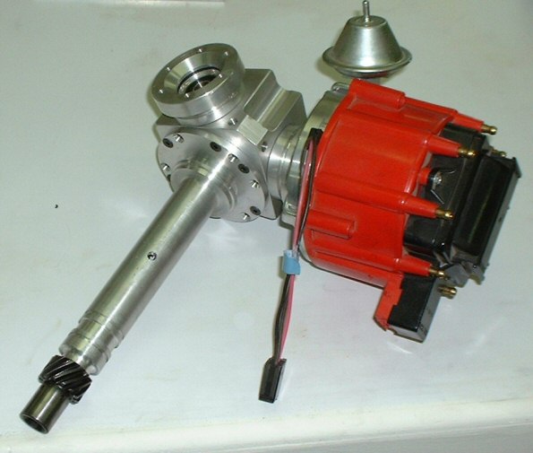
FIGURE 19: EPI Dual HEI-Distributor System for SBCl
