- Spacewalker-II Engine Mount -
Designed to Correct a Serious Aft CG Problem
NOTE: All our Products, Designs and Services are SUSTAINABLE, ORGANIC, GLUTEN-FREE, CONTAIN NO GMO's, and will not upset anyone's precious FEELINGS or delicate SENSIBILITIES.
1.0 INTRODUCTION
The purpose of this page is to present a detailed explanation of the steps involved in designing a new engine mount for a particular purpose.
In early December, 2020, EPI was engaged by a new client to design a specialty engine mount for the aircraft he was building. This client had previously rebuilt a (certified) WACO UPF-7, then built two successful experimental aircraft, and was working on completing his third. The initial weight-and-balance measurements of his essentially-completed third experimental aircraft showed a serious aft CG problem, one that had also been encountered by at least one previous builder of this plans-built (Spacewalker-II) aircraft.
The client wanted me to design an engine mount that would cause the empty CG of his Spacewalker-II to move forward to a location he had calculated to be ideal. To accomplish that, he proposed moving his O-200-A engine 20 inches further forward than is provided by the existing tubular mount structure, and to include a battery mount in the design that suitable for the Cessna battery box that is currently mounted on the fuselage between the rudder pedals.
The following text and pictures describe the procedures involved and the results of that effort.
2.0 ORIGINAL ENGINE MOUNT
Before commencing the new design, I wanted to determine what the existing max stress and deformation levels were with the original (13.375”) tubular mount that was defined in the initial drawings and pictures sent to EPI.
First, I generated a 3D model of the existing mount from the drawings provided. Next, I generated a pseudo-firewall to simulate the airframe, and a pseudo-engine to simulate the stiffness and critical external dimensions of the client's O-200-A engine.
The pseudo-firewall is a ½-inch thick steel plate that is rigidly fixed in space.
The pseudo-engine is a 7075-T6 aluminum structure designed to simulate the stiffness of the O-200-A engine assembly. It contains an octagonal structure at the approximate location of the combined engine-and-prop CG to provide surfaces for the application of vertical and horizontal G-forces. It has a simulated prop flange to enable the application of:
The pseudo-engine propeller flange is located 22 inches forward of the engine mounting face, as defined by the length of the O-200-A engine (19 inches) plus a 3 inch propeller spacer / extension.
Those analysis components are shown in Figures 1, 2, and 3.
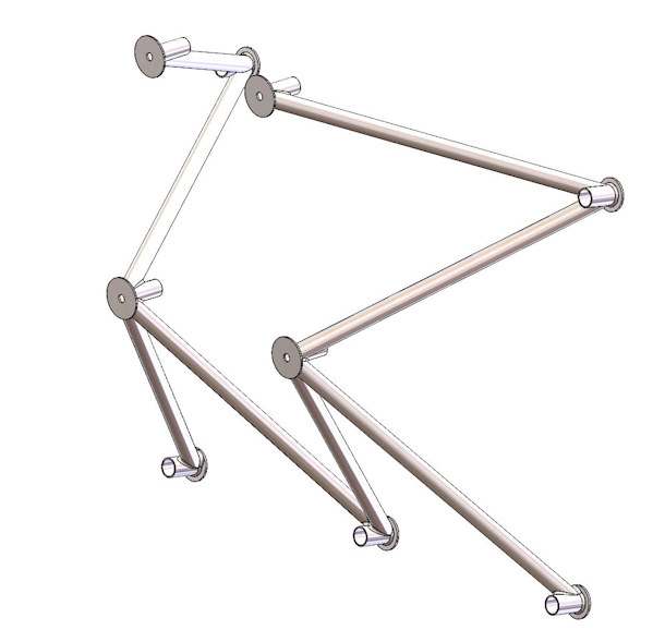
FIGURE 1: Original Spacewalker-2 Engine Mount - Locates Engine 13.75" from Firewall
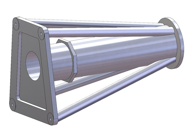
FIGURE 2: Pseudo-Engine for Analysis
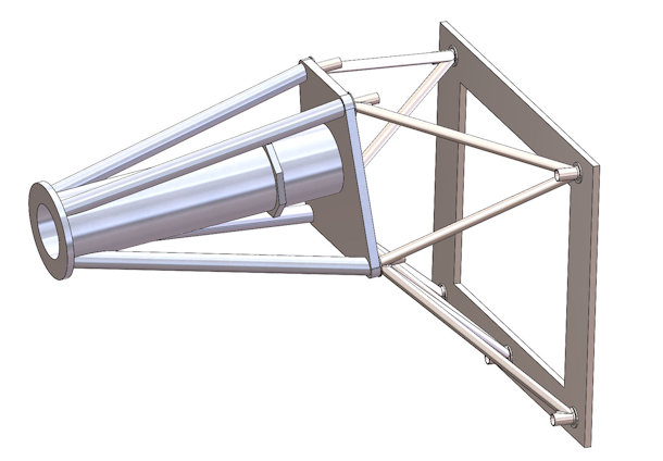
FIGURE 3: Original Mount, Pseudo-Engine, and Pseudo-Firewall - Analysis Assembly
2.1 Analysis
The assumptions made in this analysis are that the fuselage of the aircraft is very stiff, and therefore deflects an infinitesimally-small amount under the applied loads.
NOTE: In this study, there was no attempt made to determine the suitability of the airframe structure to which the original mount or the new extended mount attaches.
In order to simulate the actual airframe in the analysis, I would need a more detailed set of drawings defining the airframe from the wing spar to the firewall plus any deviations from the drawings that were made when the airframe was constructed.
It should be noted here that the dimensions from the original mount drawings yielded a firewall angle of 7.93° with respect to the engine mounting plane, whereas dimensions taken from the partial fuselage drawing showed a firewall angle of exactly 7.0°.
In keeping with the original mount design intent, I used the 7.93° value under the assumption that it was there to provide an additional nearly-one-degree nose-down angle of the thrustline relative to fuselage Waterline-0.
2.1.1 Torque Loads
For the torque loads applied to the propeller extension, I used the theoretical engine torque produced by a true 100 HP engine at 2800 RPM (187.6 lb-ft) times the 2.0 torque factor defined in FAR 23.361-c-3, for a resultant torque of 4502 lb-in.
( As an interesting aside, the O-200-D in factory trim has yet to produce more than a true 94 HP (corrected to sea-level-standard temperature and pressure conditions - 59°F and 29.92 in-hg), based on accurate independent dyno tests of several factory-new engines. In fact, the O-200-D in factory trim could not produce a true 100 HP on a cold day in Death Valley. I do not have any dyno data for the "A" version, but it is a safe bet that the much older "A" version does no better, and likely produces even less power. )
2.1.2 G-Loads
For vertical (2.50) g-loads (FAR-23.371-a-2-iii) and horizontal (1.33) g-loads (FAR 23.363-a-1), I used a weight of 286 pounds (provided by the client as 259 pounds for the engine plus 27 pounds for the prop and extension) applied at a calculated CG location of 7.06 inches forward of the engine mounting face.
NOTE: The current O-200-D engine is approximately 20 - 25 pounds lighter than the "A" version.
2.1.3 Thrust Load
I determined the applied thrust load (745 pounds) by using the assumption of an 80% efficient propeller with 100 HP applied to it, at a true airspeed of
40 MPH. I chose 40 MPH to obtain the maximum thrust value from the applied HP and assumed efficiency.
2.1.4 Gyroscopic Loads
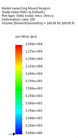
Figure 4: FEA Stress Legend
Lacking any specific propeller definition, I determined the pitch and yaw gyroscopic moments by assuming a propeller MMOI of 18 in-lb-sec², an estimated MMOI of the engine rotating assembly of 0.45 in-lb-sec², an engine crankshaft speed of 2800 rpm, with a defined 2.5 radian-per-second pitch rate and a 1.0 radian-per-second yaw rate (23.371).
Those parameters produced gyro moments of 5410 lb-in (yaw) applied around a horizontal axis and 13525 lb-in (pitch) applied around a vertical axis (centered on the prop flange), and oriented so as to provide the maximum combined load. Although the FAR-specified pitch and yaw rates would not likely be attainable at a TAS of 40 MPH, nevertheless, those combined values provide the elements of a conservative analysis.
2.1.5 Results
NOTE: The legends in the FEA diagrams below are too small to be legible in this rendition, so Figure 4 shows a close-up of the stress diagram legend. Red to orange is 15 KSI to about 12 KSI; Yellow to light green is about 12 KSI to 10 KSI; the greens are in the 10 to 5 KSI range, and the blues range from 5 KSI to zero (dark blue).
The resulting FEA showed a maximum stress level in the mount of approximately 10 ksi, located under the upper starboard firewall attach bracket, as s hown by the red arrow in Figure 5. The maximum displacement is just under 0.013” at the prop flange. Figures 5, 6, and 7 show the resultant stresses and displacements.
Note that the visual displacement scale in the following figures is set to 100 to 1 so that the actual displacements can be easily visualized.
These results demonstrate that the original mount is both strong and stiff, fully adequate for the applied loads.
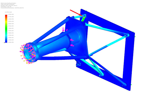
FIGURE 5: Original Spacewalker-2 Engine Mount - FEA Results -10 ksi - Ortho View
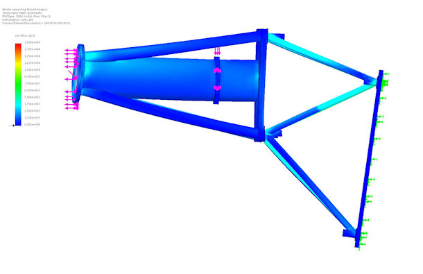
FIGURE 6: Original Spacewalker-2 Engine Mount - FEA Results - Side View
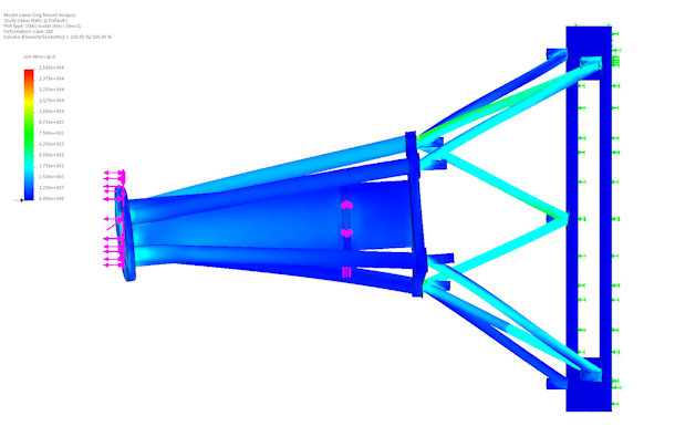
FIGURE 7: Original Spacewalker-2 Engine Mount - FEA Results - Top View
3.0 NEW EXTENDED MOUNT
Because the original mount design proved to be suitably strong and stiff, for a first pass I decided to simply extend the distance between the engine mounting plane and the firewall plane by 20 inches (from 13.375 inches to 33.375 inches), use the tubing and mount fixture sizes from the original mount, and analyze the resulting structure under the same applied loads as defined in Sections 2.1.1, 2.1.2, 2.1.3, and 2.1.4 above.
Extending the mount by 20 inches significantly reduced the angles between the tubes and their mounting fixtures. Those reduced angles made it necessary to increase the diameters and lengths of the firewall and engine mounting fixtures in order to make the junctions cleanly manufacturable. The resulting 3D-CAD model was representative of what the actual fabricated joints would be.
The first analysis using the original tubing sizes ( 0.750 dia x 0.058 wall ) proved to be sufficiently strong but was substantially lacking in adequate stiffness.
I experimented with tubing diameters and wall thicknesses, and found that sufficient strength AND stiffness was obtainable with 1.00 diameter, 0.063 wall tubing throughout.
In that configuration, the mount weighed just under 23 pounds and the peak stress was approximately 15 KSI under the combined FAR 23.371 loads.
At that point, I added the battery box mounting tray and applied a 100 pound vertical load to the horizontal surface of that structure. Figure 8 shows the analysis assembly with the battery box installed. Note that I added a generator envelope and estimated starter envelope to the pseudo-engine so as to define any space not available for additional tubes or structures.
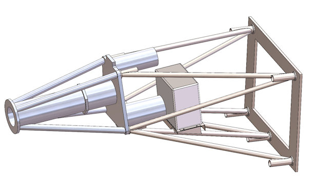
FIGURE 8: New Extended Mount with Pseudo-Engine and Battery
In order to provide the maximum forward CG shift with this new mount, the forward face of the battery box is approximately 1 inch behind the end of the generator, which means that the battery will have to be removed in order to remove the generator. The client fully agreed with that tradeoff.
The battery mount increased the weight by approximately 2.5 pounds. However, because of the large (relative) deformations in the lower-center tubes to which the battery mount is attached, the peak stresses rose to about 35 ksi, localized in the corner welds attaching the vertical battery box supports to the lower-center tubes.
Especially in a long and relatively flexible mount structure, whirl mode is a looming threat. A significant separation between the horizontal deflection rate and the vertical deflection rate is required to ward off that demon. When I analyzed the horizontal and vertical stiffnesses separately (to assure adequate separation between pitch and yaw gyroscopic resonant frequencies), I found that the stiffnesses were not adequately separated.
I adjusted the wall thicknesses where needed and achieved a 20% separation between the yaw-gyro deflection (0.010 vertical deflection of prop flange) and the pitch gyro deflection (0.012 horizontal deflection of the prop flange) for the same applied gyro moment.
Those adjustments reduced the peak stresses to about 12.6 KSI throughout, except for the same corner welds in the battery mount, which decreased to about 24 KSI. The weight of the finished mount increased to 25.4 pounds, and the mount CG is located at 15.95 inches behind the engine mounting attach plane and 6.6 inches below the crankshaft centerline.
Figures 9 and 10 show the FEA graphic results for stress and deflection. As mentioned above, the maximum stress (24 KSI) occurs at the forward corner welds of the battery mount attachment to the lower tubes. The maximum deflection under the defined loads applied was just under 0.030 inches, at the aft edge of the starter. The deflection at the prop flange was about 0.023 inches.
Again, the legends in the FEA diagrams are too small to be legible in this rendition. See Figure 4 for an enlarged Stress Legend. The Deflection Diagram Legend shows red is 0.030 inches, yellow is about 0.023, green is about 0.012, light blue is about 0.007, and dark blue ranges from 0.0025 to zero.
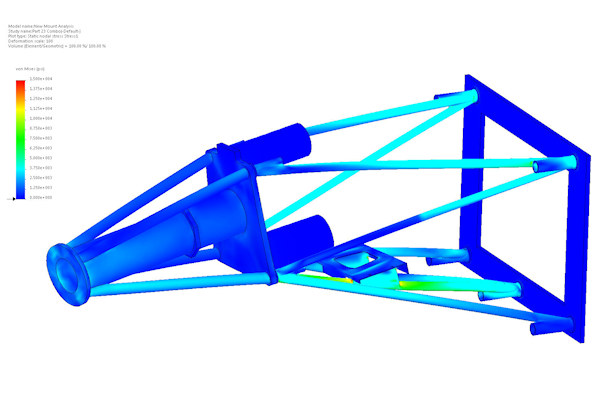
FIGURE 9: Extended Mount - FEA Stress Results - Ortho View
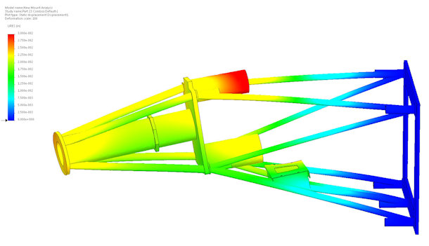
FIGURE 10: Extended Mount - FEA Deflection Results - Ortho View
After the client approved the design and analysis, I provided him with detailed fabrication drawings. He built a rigid fixture to support the construction of the new mount, acquired the requisite alloy steel material, fitted the components and TIG welded the structure.
Figure 11 shows a comparison between the original mount and the new extended mount.
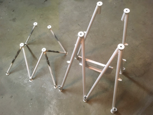
FIGURE 11: Side-by-Side Comparison: Original Mount (left) and New Mount
Figure 12 shows the new extended mount on the aircraft, with the engine installed, ready for the cowlings. Note that the battery is not installed on the battery tray I designed into the new mount (just in case). It turned out that the CG is well within the fore and aft limits with the worst-case loading configurations without moving the battery, so a substantial amount of work was saved by avoiding that change.
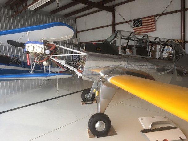
FIGURE 12: Engine Installed on Aircraft with New Extended Mount
4.0 EPILOGUE
The FAA signed off on the clent's Airworthiness Certificate on 20 July, 2021. He flew the completed aircraft for the first time on 31 July, logging a successful 40-minute flight. He is continuing a detailed, conservative test flight plan, with test cards meticulously planned and executed.
